28
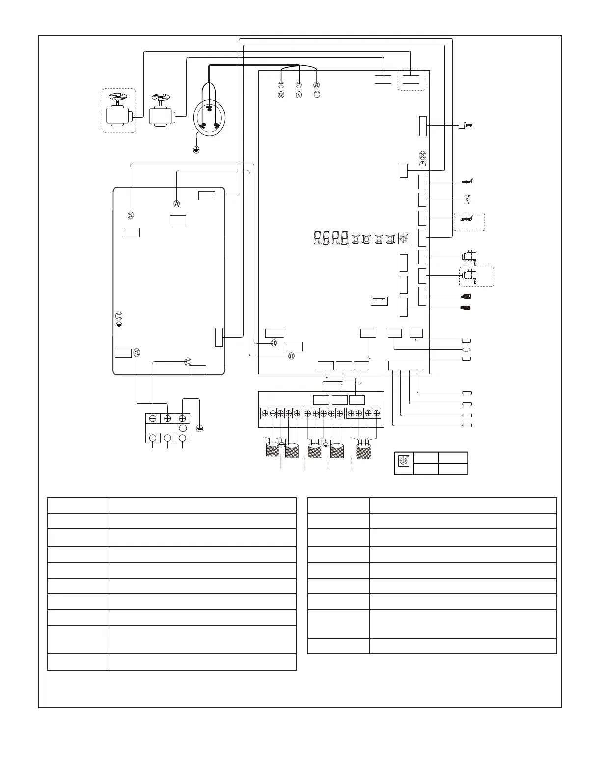
Figure 24. Typical Unit Wiring Diagram
Typical wiring diagram. Refer to
wiring diagram on the unit for
actual wiring.
SW1SW2SW3SW4
HEAT-base
ST1
DSP1 DSP2
T4
Pc
CN19
CN8
CN20
EEVC
Digital
Power Meter
IDU Comm.
IDU Comm.
PQE
X Y E
W
HyperLink
Controller
T71
TL
T8
T5
T3
L1 L2
XT1
L-IN
CN1
N-IN
CN2
BLACK RED
U
V
W
COMP.
Y/G
FAN-UP
RED
BLACK
BLUE
AC Fitter Board
Caution, low voltage wiring, do not connect to high voltage!
CN5
N-OUT
L-OUT
CN3
CN4
FAN-DOWN
ENC1
CN17
FAN-UP FAN-DOWN
CN1
CN2CN3CN4CN13CN5CN6CN12
CN16CN34CN11
CN65
USB Interface
CN7CN9CN22
CN8
CN18 CN14 CN15
CN1 CN3 CN2
CN502
CN501
O
A P
Q
E
M1
M2
C B Y
T7C1
Pe
EEVA
HEATA
H-PRO
RED
BLACK
BLUE
AHU Comm.
Inverter module Board
ENC1
2 5
3 Ton 5 Ton
ENC1 function definition:
REDBLACK
Symbol Name
COMP Compressor
H-PRO
High Pressure Switch
HEATA Crankcase heater
Pc High pressure sensor
ST1 Four-way valve
T3 Heat exchanger temperature sensor
T5 Liquid pipe temperature sensor
TL Heat exchanger liquid temperature
sensor
T7C1 Discharge temperature sensor
Symbol Name
Fan DC Fan
EEVA/C
Electronic expansion valve
Heat-base Chassis electric heating belt
Pe Low pressure sensor
XT1 Terminal block
T4 Outdoor ambient temperature sensor
T8 Heat exchanger gas temperature
sensor
T71 Suction temperature sensor
NOTE - When the unit is energized, after 10 seconds, the main board display will light up.
 Loading...