29
Figure 25. Typical REAL System Power Wiring
VRF Indoor Unit
Power Supply
(208/230V 1PH 60Hz)
Power wire between indoor units
Incoming
Electrical
Supply
J- Box
J- Box
VRF
Indoor
Unit
VRF
Indoor
Unit
Service
Disconnect
L1 L2
Fuse
L2L1
Service
Disconnect
L1 L2
Fuse
L2L1
J- Box
Air Handler/Furnace
Connected to
AHU
Control
Kit
Incoming
Electrical
Supply
Air Handler/Furnace
Power Supply
(Depends on Unit)
REAL Outdoor Unit
Power Supply
(208/230V 1PH 60Hz)
Incoming
Electrical
Supply
J- Box
J- Box
AHU
Control
Kit
Incoming
Electrical
Supply
AHU Control Kit
Power Supply
(90-250V 1PH 60 Hz)
Service
Disconnect
L1 L2
Fuse
L2L1
Service
Disconnect
L1 L2
Fuse
L2L1
Outdoor Unit
Service
Disconnect
L1 L2
Fuse
L2L1
Must be on its own breaker.May be combined on one breaker if power supplies match and local codes allow.
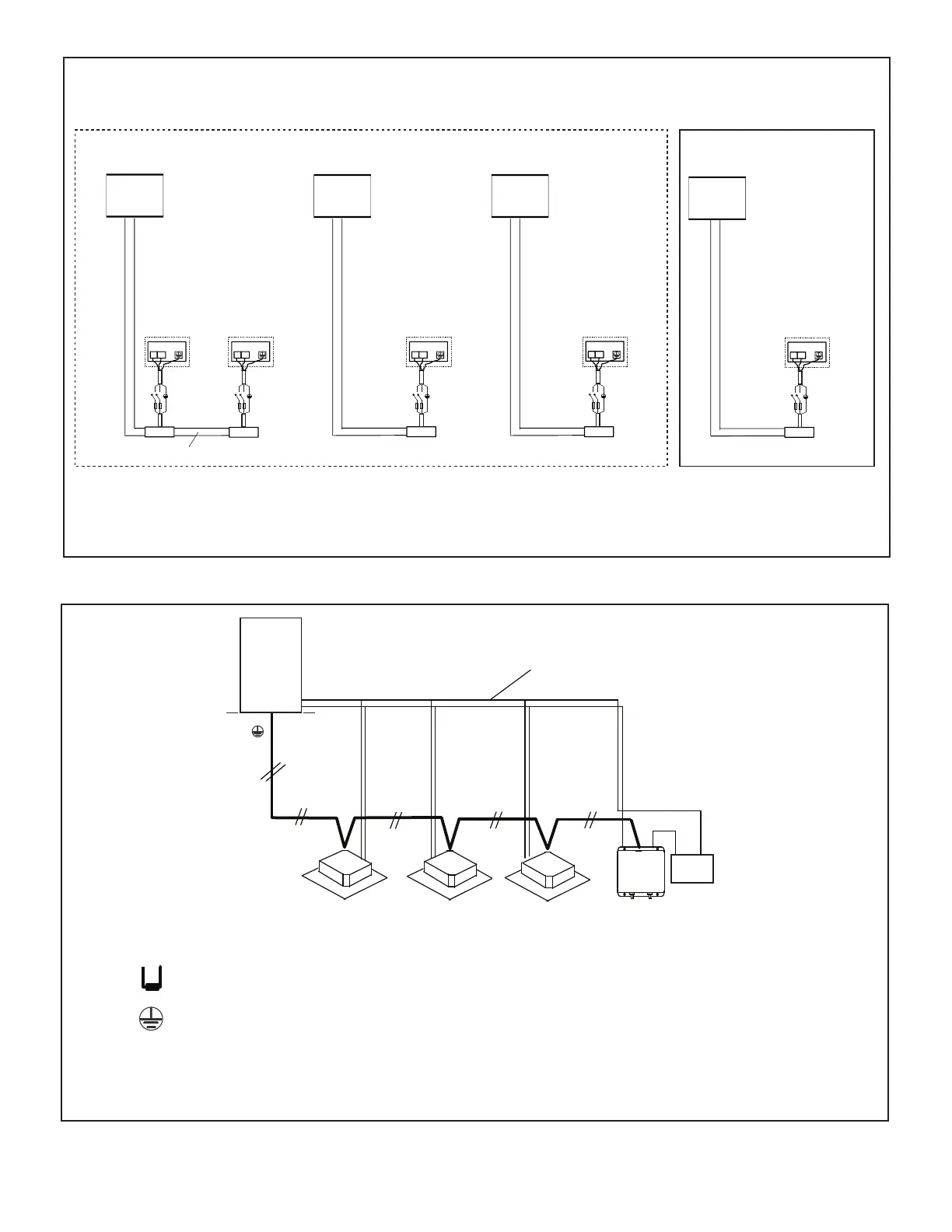
Figure 26. Typical VRF Indoor Unit and AHU Control Kit Communication Wiring
Always follow NEC/CEC and Local Codes.
(PQ)
Refrigerant Piping
Coil
AHU
Control Kit
P Q
All Drain Wires will connect from outdoor unit chassis to indoor unit chassis at the end of the signal
run.
18 GA., stranded, 2-conductor, shielded control wire (polarity sensitive).
Typical Wiring Diagram, NEC/CEC and Local Codes apply.
Install a terminating resistor (Ω120) on terminals P&Q on the indoor unit
which is furthest from the outdoor unit.
VRF
Indoor Unit
Outdoor
Unit
VRF
Indoor Unit
VRF
Indoor Unit
 Loading...