42
Service & Setup Functions
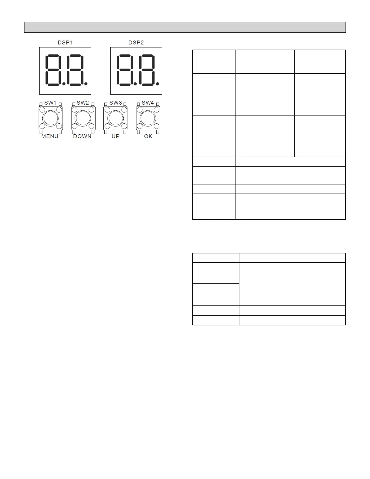
Table 15. Digital Display Output
Outdoor Unit
State
Parameters
Displayed on
DSP1
Parameters
Displayed on
DSP2
Standby
Unit’s Address
The number of
indoor units in
communication
with the
outdoor unit
Normal
Operation
-
Running
Speed of the
compressor in
rotations per
second
Error Protection code
In menu
mode
Displays menu mode code
Spot check Displays system check code
Standby with
low energy
consumption
No display
NOTE - Press any button one time to activate
display.
Table 16. Function of Buttons SW1 to SW4
Button Function
SW3 (UP)
In menu mode: previous and next
buttons for menu modes.
Not in menu mode: previous
and next buttons for spot check
information.
SW2 (DOWN)
SW1 (MENU) Enter / exit menu mode.
SW4 (OK) Conrm to enter specied menu.
 Loading...