EasyManua.ls Logo

Lennox VPB H4-3P Series

Lennox VPB H4-3P Series
36 pages
To Next Page IconTo Next Page
Loading...
1
INSTALLATION/OPERATION
INSTRUCTIONS
Mini-VRF Heat Pump
VPB***H4-3P
VRF SYSTEMS
OUTDOOR UNITS
507998-01
10/2019
THIS MANUAL MUST BE LEFT WITH THE
OWNER FOR FUTURE REFERENCE
These instructions are intended as a general guide and do
not supersede local codes in any way. Consult authorities
having jurisdiction before installation.
Shipping and Packing List
General
Check the components for shipping damage. If you
nd any damage, immediately contact the last car-
rier. Package 1 of 1 contains the following:
1 - Assembled Mini-VRF heat pump outdoor unit
1 - Outdoor unit installation instruction
The Mini-VRF heat pump outdoor units are matched
with up to nine indoor units to create a VRF (variable
refrigerant ow) system that uses R-410A refrigerant.
Refer to the Product Specication bulletin (EHB) for
the proper use of these heat pumps with matching
indoor units, header pipes, branch pipes, line sets
and controls.
These instructions are intended as a general guide
and do not supersede local or national codes in any
way. Authorities having jurisdiction should be con-
sulted before installation.
WARNING
Improper installation, adjustment, alteration, ser-
vice or maintenance can cause property damage,
personal injury or loss of life.
Installation and service must be performed by a li-
censed professional HVAC installer, service agency
or the gas supplier.
Failure to follow safety warnings and these instruc-
tions exactly could result in property damage, dan-
gerous operation, serious injury, or death.
Any additions, changes, or conversions required in
order for the appliance to satisfactorily meet the ap-
plication needs must be made by a licensed profes-
sional HVAC installer (or equivalent) using factory-
specied parts.
Do not use this system if any part has been under
water. A ood-damaged appliance is extremely dan-
gerous. Immediately call a licensed professional
HVAC service technician (or equivalent) to inspect
the system and to replace all controls and electrical
parts that have been wet, or to replace the system, if
deemed necessary.
CAUTION
As with any mechanical equipment, contact with sharp
sheet metal edges can result in personal injury. Take
care while handling this equipment and wear gloves and
protective clothing.
IMPORTANT
The Clean Air Act of 1990 bans the intentional venting
of refrigerant (CFC’s and HCFC’s) as of July 1, 1992.
Approved methods of recovery, recycling or reclaiming
must be followed. Fines and/or incarceration may be
levied for non-compliance.
CAUTION
To ensure proper system performance and reliability,
Lennox does not recommend operation of VRF sys-
tems during any phase of construction. Construction
debris, low temperatures, harmful vapors, and opera-
tion of the unit with misplaced lters can damage the
units. Failure to follow these guidelines will result in the
warranty being voided.
©2019 Lennox Industries Inc. Dallas, Texas, USA
VRF
Question and Answer IconNeed help?

Do you have a question about the Lennox VPB H4-3P Series and is the answer not in the manual?

Lennox VPB H4-3P Series Specifications

General IconGeneral
BrandLennox
ModelVPB H4-3P Series
CategoryHeat Pump
LanguageEnglish

Summary

General Product Information

Mini-VRF Heat Pump Overview

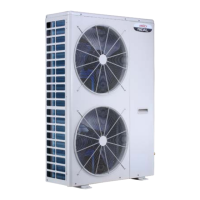
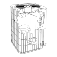
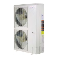
Describes the Mini-VRF heat pump outdoor units and their compatibility with indoor units.

Shipping and Packing Contents

Details the components included in Package 1 of 1 for the outdoor unit.

Safety and Identification

Electrical Safety Requirements

Warns about electrical hazards and safe handling practices for the unit and its components.

Model Number Decoding

Explains the meaning of each segment in the VRF system's model number.

System Piping Design

Piping Design and Modification Procedures

Emphasizes the importance of following the engineered piping design and notifying Lennox of any modifications.

Unit Dimensions and Weight

Dimensional Data and Center of Gravity

Provides detailed dimensional data and corner weights for the outdoor unit.

Installation Clearances

Clearances for Single Unit Installation

Specifies minimum clearances required for a single outdoor unit installation.

Clearances for Parallel Unit Installations

Details clearances for side-by-side and back-to-back parallel installations.

Outdoor Unit Placement

Site Selection Considerations

Offers advice on selecting an optimal site for the outdoor unit, considering sound and interference.

Lifting and Mounting Guidelines

Provides instructions on safely lifting the unit and mounting it on slabs or roofs.

Securing and Draining

Securing Methods for Outdoor Unit

Explains how to secure the outdoor unit to slabs, frames, or wall brackets.

Condensate Drain System

Describes the function of factory-provided drains and protection against pests.

Cold Climate Installation

Protection from Wind and Snow

Provides guidance on positioning and protecting the unit from wind, snow, and ice buildup.

Prevailing Winds Management

Wind Barrier Installation Techniques

Details methods for protecting the unit coil from prevailing winter winds using barriers or enclosures.

Buried Refrigerant Pipe Protection

Requirements for Buried Pipes

Specifies insulation and sealed, watertight conduit requirements for buried refrigerant lines.

Indoor Installation Requirements

Indoor Unit Placement and Clearances

Outlines requirements for installing outdoor units indoors, including ductwork and clearances.

Refrigerant Piping Connections

Safety During Piping Connections

Emphasizes refrigerant leak safety, R410A usage, and preventing contaminants during connection.

Pipe Sizing and Insulation Requirements

Lists refrigerant pipe connection sizes and stresses the need for individual insulation of liquid and gas lines.

Refrigerant Pipe Length Limits (Branch Pipe)

Maximum Permitted Piping Lengths

Details total and individual pipe length limits for systems using branch pipes.

Maximum Height Differences

Specifies allowable height differences between outdoor and indoor units and between indoor units.

Refrigerant Pipe Length Limits (Header Pipe)

Maximum Permitted Piping Lengths

Defines maximum pipe lengths for systems using a single header pipe kit.

Maximum Height Differences

Outlines allowable height variations for systems with one header pipe kit.

Refrigerant Pipe Length Limits (Two Header Pipes)

Maximum Permitted Piping Lengths

Lists maximum pipe lengths for systems utilizing two header pipe kits.

Maximum Height Differences

Specifies maximum height differences for systems with two header pipe kits.

Refrigerant Pipe Length Limits (Three Header Pipes)

Maximum Permitted Piping Lengths

Details maximum pipe lengths for systems using three header pipe kits.

Maximum Height Differences

Outlines maximum height differences for systems with three header pipe kits.

Refrigerant Pipe Selection Guide

Main Outdoor Unit Pipe Sizing

Provides guidance on selecting liquid and gas pipe diameters based on capacity and length.

Indoor Unit Combination Ratios

Details acceptable indoor unit combination ratios and total piping lengths.

Indoor Main Pipe Sizing

Specifies pipe diameters for indoor main pipes based on downstream capacity.

Indoor Unit Pipe Diameter Selection

Lists gas and liquid pipe diameters for different types and sizes of indoor units.

Refrigerant System Procedures

Pressure Testing Procedures

Details the specifications and duration for pressure testing the refrigerant system.

System Evacuation Procedure

Outlines the triple evacuation procedure using a micron gauge to ensure system dryness.

Additional Refrigerant Charge Calculation

Liquid Line Charge Adjustment

Explains how to calculate additional refrigerant charge based on liquid line pipe size and length.

Branch Pipe Kit Charge Adjustment

Provides guidance for additional charge calculation related to VMDB or V33B indoor unit capacity ratios.

Wiring Connection Requirements

Electrical Safety and Wiring Practices

Covers essential safety warnings, wiring requirements, and precautions for electrical connections.

Power and Communication Wiring Terminals

Details the terminal strips for power and communication wiring and connection guidelines.

Outdoor Unit Main Control Board

Typical Wiring Diagram and Components

Identifies key components and provides a typical wiring diagram for the outdoor unit main control board.

Outdoor Unit Main Control Board Details

Control Board Component Identification

Highlights specific components and switches on the outdoor unit's main control board.

Network Addressing and Commissioning

Outdoor Unit Network Address Settings

Explains how the outdoor unit assigns addresses to connected indoor units and manual setting options.

Indoor Unit Address Configuration

Details automatic/manual address configuration and procedures for clearing indoor unit addresses.

Priority Mode Configuration Options

Describes settings for priority modes like Outdoor Ambient, Cooling, Heating, and System Demand.

Diagnostic Data Access

Viewing System Data via SW2

Explains how to use SW2 to view system parameters and performance data.

Service and Setup Functions

Forced Cooling Operation Guide

Details how to initiate forced cooling, its effects on unit operation, and indoor unit status.

Manual Defrost Procedure Guide

Explains the process for initiating manual defrost and its impact on unit operation.

Service Menu Navigation

Accessing and Navigating Service Menus

Guides users on how to navigate Level 1 and Level 2 menus using buttons SW1 and SW2.

Service Menu Function Details

Emergency Stop and Test Operations

Describes how to cancel emergency stops and perform forced cooling/heating tests.

Priority and Temperature Settings

Explains Auto Priority, Compressor Lockout Temperature, and Indoor Unit Temperature Unit settings.

Technical Support Resources

Contact Information and App Downloads

Provides phone numbers, email, website, and app download links for technical support.

Related product manuals