27
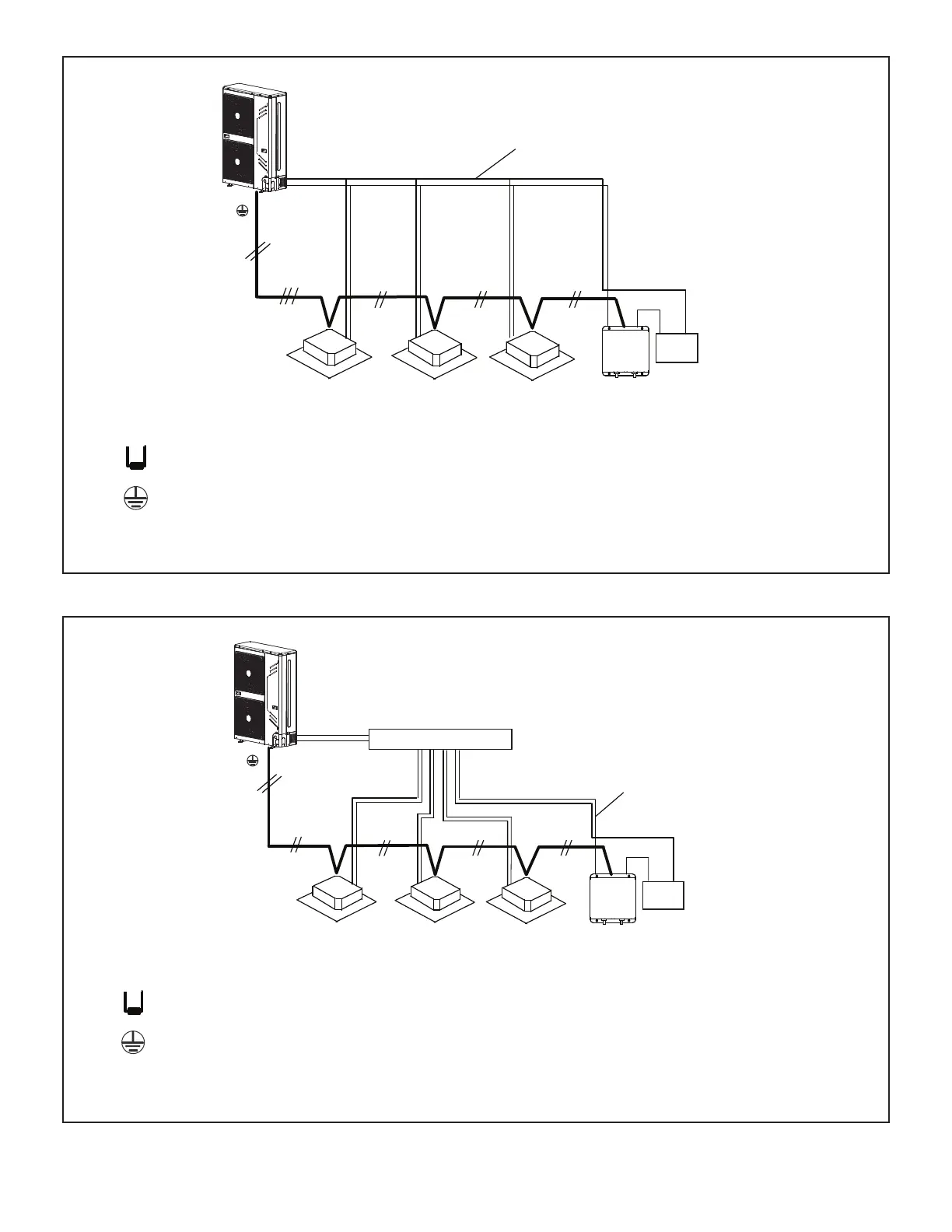
Figure 27. Typical Communication Wiring
Outdoor Unit
(PQ)
Refrigerant Piping
Coil
AHU
Control Kit
P Q
All Drain Wires will connect from outdoor unit chassis to mode selection box chassis at the end of
the signal run.
18 GA., stranded, 2-conductor, shielded control wire (polarity sensitive).
Typical Wiring Diagram, NEC/CEC and Local Codes apply.
Install a terminating resistor (Ω120) on terminals P&Q on the indoor unit
which is furthest from the outdoor unit.
Indoor UnitIndoor UnitIndoor Unit
Outdoor Unit
Refrigerant Piping
(PQ)
Coil
AHU
Control Kit
Indoor UnitIndoor UnitIndoor Unit
P Q
All Drain Wires will connect from outdoor unit chassis to indoor unit chassis at the end of the signal
run.
18 GA., stranded, 2-conductor, shielded control wire (polarity sensitive).
Typical Wiring Diagram, NEC/CEC and Local Codes apply.
Install a terminating resistor (Ω120) on terminals P&Q on the indoor unit
which is furthest from the outdoor unit.
Header Pipe Kit
V8HDRK04
Figure 28. Typical Communication Wiring
 Loading...