28
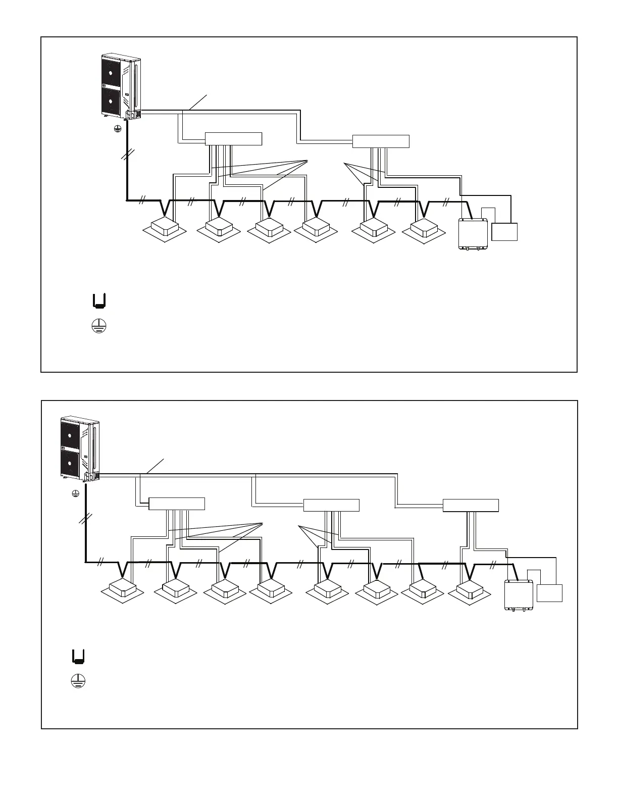
Figure 30. Typical Communication Wiring
Refrigerant Piping
Outdoor Unit
(PQ)
Refrigerant Piping
P Q
All Drain Wires will connect from outdoor unit chassis to indoor unit chassis at the end of the signal
run.
18 GA., stranded, 2-conductor, shielded control wire (polarity sensitive).
Typical Wiring Diagram, NEC/CEC and Local Codes apply.
Install a terminating resistor (Ω120) on terminals P&Q on the indoor unit
which is furthest from the outdoor unit.
Coil
AHU
Control Kit
Indoor UnitIndoor UnitIndoor UnitIndoor UnitIndoor UnitIndoor Unit Indoor UnitIndoor Unit
Header Pipe Kit
V8HDRK04
Header Pipe Kit
V8HDRK04
Header Pipe Kit
V8HDRK04
Refrigerant Piping
(PQ)
Outdoor Unit
Refrigerant Piping
Coil
AHU
Control Kit
Indoor UnitIndoor UnitIndoor Unit
Indoor UnitIndoor UnitIndoor Unit
P Q
All Drain Wires will connect from outdoor unit chassis to indoor unit chassis at the end of the signal
run.
18 GA., stranded, 2-conductor, shielded control wire (polarity sensitive).
Typical Wiring Diagram, NEC/CEC and Local Codes apply.
Install a terminating resistor (Ω120) on terminals P&Q on the indoor unit
which is furthest from the outdoor unit.
Header Pipe Kit
V8HDRK04
Header Pipe Kit
V8HDRK04
Figure 29. Typical Communication Wiring
 Loading...