EasyManua.ls Logo

Lennox XC14 Series User Manual

Lennox XC14 Series
22 pages
To Next Page IconTo Next Page
Page #1 background imageLoading...
Page #1 background image
Page 1
©2007 Lennox Industries Inc.
Corp. 0704−L2
XC14
Service Literature
Revised 07−2008
XC14 SERIES UNITS
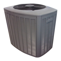
The XC14 is a high efficiency residential split−system con-
densing unit, which features a scroll compressor and
R−410A refrigerant. XC14 units are available in sizes rang-
ing from 1 1/2 through 5 tons. The series is designed for use
with an expansion valve or RFC (approved for use with
R−410A) in the indoor unit. This manual is divided into sec-
tions which discuss the major components, refrigerant sys-
tem, charging procedure, maintenance and operation se-
quence.
Information contained in this manual is intended for use by
qualified service technicians only. All specifications are sub-
ject to change.
WARNING
Improper installation, adjustment, alteration, service
or maintenance can cause property damage, person-
al injury or loss of life. Installation and service must
be performed by a qualified installer or service
agency.
WARNING
Warranty will be voided if covered equipment is re-
moved from original installation site. Warranty will
not cover damage or defect resulting from:
Flood, wind, lightning, or installation and operation
in a corrosive atmosphere (chlorine, fluorine, salt,
recycled waste water, urine, fertilizers, or other dam-
aging chemicals).
DANGER
Shock Hazard
Remove all power at disconnect
before removing access panel.
Single phase XC14 units use single-
pole contactors. Potential
exists for electrical shock resulting
in injury or death.
Line voltage exist at all components
(even when unit is not in operation).
IMPORTANT
Operating pressures of this R−410A unit are higher
than pressures in R−22 units. Always use service
equipment rated for R410A.
TABLE OF CONTENTS
General Page 1. . . . . . . . . . . . . . . . . . . . . . . . . . . .
Specifications / Electrical Data Page 2. . . . . . . . .
I Application Page 4. . . . . . . . . . . . . . . . . . . . . . . . .
II Unit Components Page 4. . . . . . . . . . . . . . . . . .
III Refrigeration System Page 8. . . . . . . . . . . . . . .
IV Charging Page 9. . . . . . . . . . . . . . . . . . . . . . . . .
V Service and Recovery Page 21. . . . . . . . . . . . . .
VI Maintenance Page 21. . . . . . . . . . . . . . . . . . . . . .
VII Wiring and Sequence of Operation Page 22. .
Question and Answer IconNeed help?

Do you have a question about the Lennox XC14 Series and is the answer not in the manual?

Lennox XC14 Series Specifications

General IconGeneral
RefrigerantR-410A
StagesSingle-Stage
Cooling Capacity (BTU/h)18, 000 - 60, 000
Heating Capacity (BTU/h)18, 000 - 60, 000
Cooling EfficiencyUp to 16 SEER
Heating EfficiencyUp to 9.0 HSPF
CompressorScroll Compressor
Warranty10-year limited warranty on compressor and 5-year limited warranty on parts

Summary

Unit Specifications

Electrical Data

Details electrical specifications including voltage, amps, and power factor for XC14 units.

Optional Accessories

Lists optional accessories available for the XC14 series units.

Model-Specific Specifications

Model-Specific Electrical Data

Electrical specifications tailored for specific XC14 model ranges, detailing amps and power factor.

Application Overview

Unit Components Identification

Louvered Panel Handling

Step-by-step instructions for safely removing and installing the unit's louvered panels.

Control Box Components

ESD Precautions

Safety guidelines to prevent damage to electronic components from electrostatic discharge during service.

Control Box Component Details

Details the compressor contactor, dual capacitor, timed off control, and start kit options.

Scroll Compressor Description

Compressor Sound Insulation

Information on the sound cover and pad used to reduce noise from the scroll compressor.

Scroll Compressor Mechanism

Explains the internal mechanism and operation of the scroll compressor design.

Filter Drier Function

Condenser Fan Motor Details

Condenser Fan Motor Safety

Critical safety warning regarding electrical hazards when servicing the condenser fan motor.

Refrigerant System Overview

Refrigerant Line Plumbing

Details the refrigerant piping connections and recommended line sets for XC14 units.

Compressor Protection Components

Details thermostats, pressure switches, and loss of charge switches for system protection.

Service Valve and Schrader Port Access

Instructions for accessing and operating service valves and Schrader ports on the unit.

Refrigerant Charging Procedures

Leak Testing the System

Procedure for checking the refrigerant system for leaks after installation or service.

Closing Service Valves

Instructions on how to properly close the service valves after charging or testing.

Ball Valve Operation

Description of the ball valve used for vapor lines on 5-ton units.

System Evacuation Process

Electronic Leak Detection

Instructions for using an electronic leak detector to find refrigerant leaks.

Pressurization Safety Warnings

Critical safety warnings regarding the use of gases for pressurizing refrigeration lines.

Explosion Hazard Warning

Warning about the explosion danger when using high-pressure gases like nitrogen for system pressurization.

R-410A Charging and Oil

Polyol Ester Oil Compatibility

Notes on the compatibility and use of polyol ester oil with R-410A systems.

Factory Refrigerant Charge

Information on the factory-provided refrigerant charge and adjustments for line set length.

Equipment Damage Prevention

Cautionary advice to avoid equipment damage from improper vacuum operation.

Handling Units Void of Charge

Delta-T Airflow Check

Charging Method Determination

Weigh-In Charging Method

Procedure for weighing in refrigerant based on line length and outdoor temperature.

Superheat Method for RFC Units

Using the superheat method to charge RFC units, including required measurements and table comparison.

Approach Method for TXV Units

Subcooling Method for TXV Units

Normal Operating Pressures

HFC-410A Pressure-Temperature Chart

Charging Specific XC14 Models

Indoor Coil Airflow Check (Delta-T)

Procedure to check indoor coil airflow using Delta-T and adjust fan speed for optimal performance.

Determining Refrigerant Charge Method

Weigh-In Method for TXV Units

Instructions for weighing in refrigerant for TXV units based on line length.

Approach Method for TXV Units

Subcooling Method for TXV Units

Weigh-In Method for Fixed Orifice Units

Superheat Method for Fixed Orifice Units

Normal Operating Pressures (TXV & RFC)

HFC-410A Pressure-Temperature Chart

Service and Refrigerant Recovery

Refrigerant System Moisture Precautions

Critical warnings about POE oils absorbing moisture and keeping the system sealed.

R-410A Recovery Equipment

Importance of using recovery machines specifically rated for R-410A refrigerant.

Moisture Removal from Oil

Note that system evacuation alone cannot remove moisture absorbed by compressor oil; drier replacement is key.

Routine Maintenance Procedures

Outdoor Unit Maintenance

Cleaning, inspection, and checks for the outdoor unit, including coil, fan motor, and wiring.

Indoor Coil Maintenance

Instructions for cleaning the indoor coil and checking connecting lines for oil leaks.

Indoor Unit Maintenance

Tasks for the indoor unit, including filter changes, blower speed adjustment, and belt checks.

Wiring Diagrams and Operation Sequence

Cooling Operation Sequence

Step-by-step explanation of the cooling cycle, from thermostat call to unit shutdown.

Related product manuals