Page 47
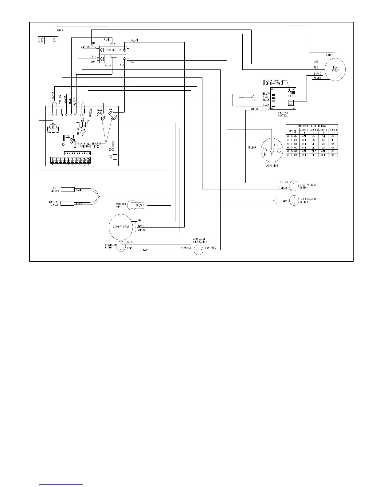
XP21
CRANKCASE HEATER (HR1)
Compressors in all units are equipped with a 70 watt belly
band type crankcase heater. HR1 prevents liquid from ac
cumulating in the compressor. HR1 is controlled by the
crankcase heater thermostat.
CRANKCASE HEATER THERMOSTAT (S40)
Thermostat S40 controls the crankcase heater in all units.
S40 is located on the liquid line. When liquid line tempera
ture drops below 50°F the thermostat S40 closes
energizing HR1. The thermostat will open, de-energizing
HR1 once liquid line temperature reaches 70°F .
REVERSING VALVE (L1)
The primary components of the reversing valve are revers
ing valve, solenoid and wiring harness.
TO COMPRESSOR
DISCHARGE LINE
LINE TO OUTDOOR
COIL
SUCTION LINE (TO
COMPRESSOR)
VAPOR LINE (TO SERVICE VALVE)
SOLENOID
IMPORTANT — CONFIRM CORRECT CONNECTIONS OF
REFRIGERANT LINES TO REVERSING VALVE BEFORE
BRAZING IN VALVE.
IMPORTANT — ENSURE NEW REVERSING VALVE IS INSTALL EXACTLY AS ORIGINAL
VALVE.
1. WHEN THE SOLENOID IS ENERGIZED (ON), THE
EVAPORATOR (INDOOR COIL — E) REFRIGERANT
PRESSURE IS DIRECTED TO THE SUCTION (S) BACK
TO THE COMPRESSOR.
2. WHEN THE SOLENOID IS DE-ENERGIZED (OFF),
REFRIGERANT PRESSURE IS DIRECTED FROM THE
CONDENSER (OUTDOOR COIL (C) TO THE SUCTION
(S) BACK TO THE COMPRESSOR.
REVERSING VALVE
OPERATION
Figure 20. Typical Reversing Valve Components and Operation
 Loading...