Page 9
XP21
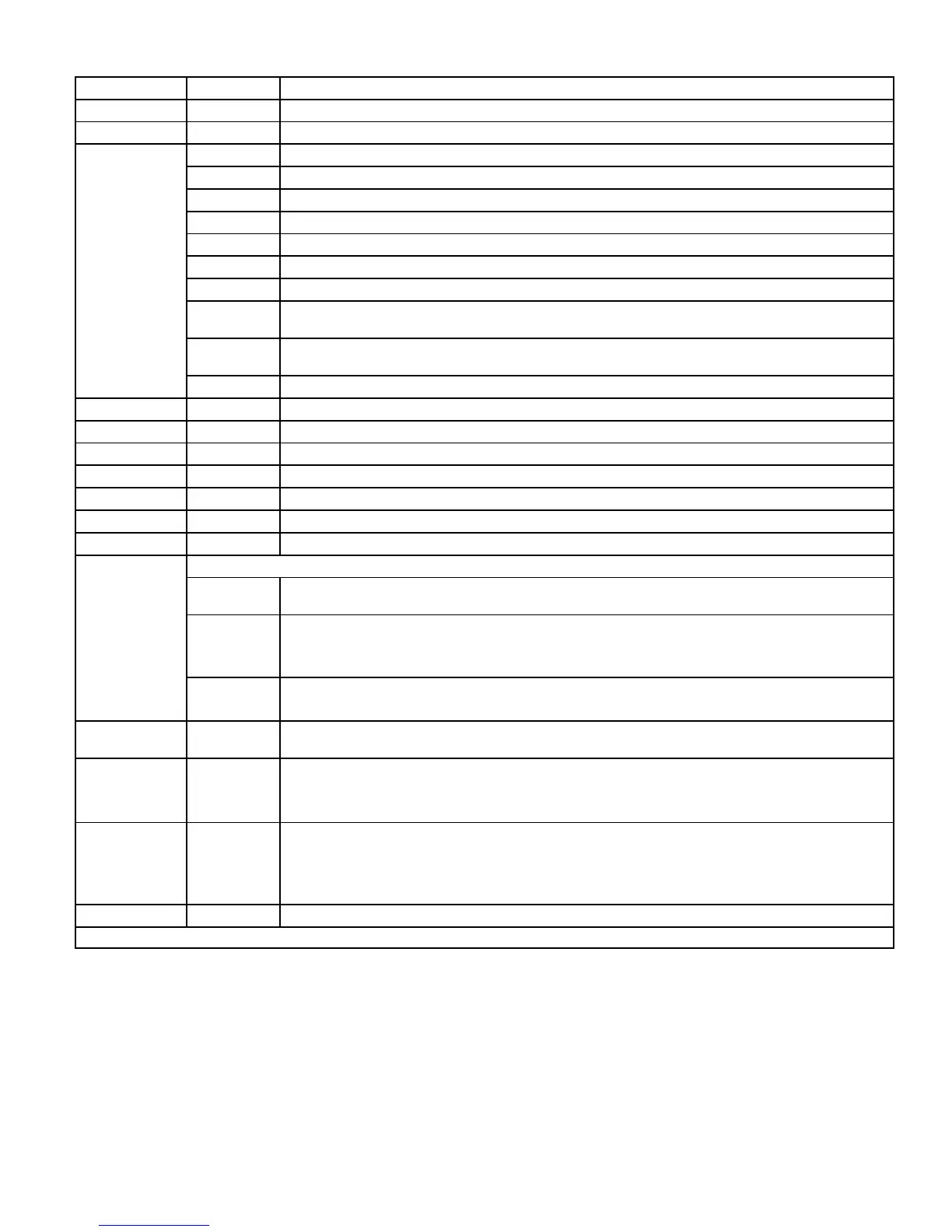
Table 2. 101796-xx Jumpers, Loop and Terminal Descriptions
Control ID Label Description
E12 PSC Fan 240 VAC output connection for outdoor fan.
E16 PSC Fan 240 VAC input connection for outdoor fan.
E18
W 24VAC output for defrost auxiliary heat output.
L Thermostat service light connection.
Y2 24VAC thermostat input/output for second stage operation of the unit.
Y1 24VAC thermostat input for first stage operation of the unit.
O 24VAC thermostat input for reversing valve operation
DS Humiditrol Input
C 24VAC system common
i- Input/Output - RSBus data low. Used in communicating mode only with compatible indoor thermostat.
i+ Input/Output - RSBus data high. Used in communicating mode only with compatible indoor thermostat.
R 24VAC system power input
E19 and E20 O OUT 24 VAC output connection for reversing valve.
E21 and E22 LO-PS Connection for low-pressure switch (2.4 milliamps @ 18VAC)
E31 and E32 Y1 OUT 24 VAC common output, switched for enabling compressor contactor.
E24 and E25 HS-PS Connection for high-pressure switch.
E26 FAN 1
First Stage and second stage basic and precision dehumidification ECM fan motor 24VDC output connection
1.
E27 FAN 2 Second stage basic and precision dehumidification ECM fan motor 24VDC output connection 2.
E28 FAN C ECM common connection for ECM fan.
E30
Six position square pin header. P4 provides connections for the temperature sensors.
DIS (YELLOW)
PINS 5 and 6
DIS 5 — Discharge line temperature sensor supply.
DIS 6 — Discharge line temperature sensor return.
Range is 35ºF to 310ºF. Sensor is clipped on a 1/2” copper tube.
AMB (BLACK)
Pins 3 and 4
AMB 3 — Outdoor ambient temperature sensor supply.
AMB 4 — Outdoor ambient temperature return.
Range is 40ºF to +140ºF
COIL (BROWN)
Pins 1 and 2
COIL 1 — Outdoor coil temperature sensor supply.
COIL 2 — Outdoor coil temperature sensor return
Range is 40ºF to 140ºF. Sensor is clipped on a 5/16” copper return bend.
E33 Field Test
This jumper allows service personnel to defeat the timed off control, initiate or terminate a defrost and field
programming of unit capacity feature and clears lockouts.
E34 Y2 Solenoid
Keyed plug header used for second-stage compressor output. Sequence for Y2 solenoid coil operations:
Five (5) second delay after Y2 is ON.
Two (2) seconds full 24VDC.
Pulsing voltage to keep solenoid engage
E37 Comp Shift Delay
The heat pump control has a field-selectable function to reduce occasional sounds that may occur while the
unit is cycling in and out of the defrost mode. When a jumper is installed on the DELAY pins (E37), the
compressor will be cycled off for 30 seconds going in and out of the defrost mode. Units are shipped with
jumper installed on DELAY pins. If no jumper is installed, the 30 second compressor shift delay is not active.
On outdoor control part number 101796-04 and later, removing jumper also enables the fan cycling
option.
E47
50*
70
90
100
Seven position square pin header. E47 provides selection of the defrost terminate temperature based on the
position of the selection jumper. The defrost termination temperature is measured by the RT21
coil tempera
ture sensor. The jumper termination pin is factory set at 50°F (10°C). If the temperature jumper is not installed,
the default termination temperature is 90°F (32°C).
E48
55
50
45
40 *
(This option is only available on outdoor control part numbers 101796-01 through -03) Five position
square pin header. If the first-stage compressor output is active in heating mode and the outdoor ambient
temperature is below the selected compressor lock-in temperature, the second-stage compressor solenoid
outputs will be energized without the Y2 input. If the jumper is not present on E48, the default lock-in
temperature of 40ºF will be used.
 Loading...