Install hardware | Stage 2
A
B
1
2
Unified configuration
• Install the rail kits, as needed, and then install and
secure your system using the instructions included with the kit.
• Attach cable management devices (as shown).
• Place the bezel on the front of the system.
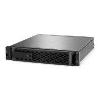
Install system in a rack
2
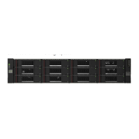
Rear view of the controllers
1
3
Cable controller for cluster
4
2
2
3
1
1
Ethernet cables
Ethernet cables
Cluster interconnect cables
Power cables
4
Connect both power cords
1
2
Retaining clipsRetaining clips
2
To data network
switches
3
To management
network switches
1
A
B
1
2
Ethernet configuration
10 GbE
network
cables
Optical
network
cables
OR
Switchless cluster
Ethernet cables for use
with Ethernet configuration
Unified
configuration
For Unified configuration
For Ethernet configuration
DO NOT turn on the power supply switches.
Strap the cables to the cable
management arms. (not shown)
For switchless cluster
Connect port e0a to port e0a and port e0b
to port e0b.
Connect ports e0c and e0d OR ports e0e
and e0f to the data network switches.
Connect ports e0c and e0e OR ports e0d
and e0f to the data network switches.
Connect the wrench port (e0M)
on both controller modules to the
management subnet switches.
Connect the power cables to both power supplies.
• Use the retaining clips.
• Connect power cables to different power sources.
For switched cluster
Connect port e0a and port e0b to the
cluster interconnect switches.
1
To cluster interconnect
switches
Switched cluster
Unified
configuration
2
To data network
switches
3
To management
network switches

 Loading...