“Remove the solid-state drive (SSD) plate” on page 33
“Remove the solid-state drive (SSD)” on page 34
“Remove the battery pack” on page 35
“Remove the Wi-Fi card” on page 35
“Remove the hard disk drive (HDD) module” on page 36
“Remove the memory module” on page 37
“Remove the heat sink” on page 38
“Remove the fan” on page 38
“Remove the I/O board” on page 39
“Remove the Kensington lock” on page 40
“Remove the RTC battery” on page 41
“Remove the speakers” on page 42
“Remove the system board and the I/O board cable” on page 42
“Remove the strip cover” on page 44
“Remove the LCD module” on page 45
Go to
https://support.lenovo.com/partslookup to look up the Lenovo part numbers of the following
replacement part:
Upper case (with keyboard and touch pad)
Disassemble the LCD module
The LCD module as a whole is not an FRU. Instead, it contains FRUs as its components. Before
disassembling the LCD module, make sure it has been detached from the upper case.
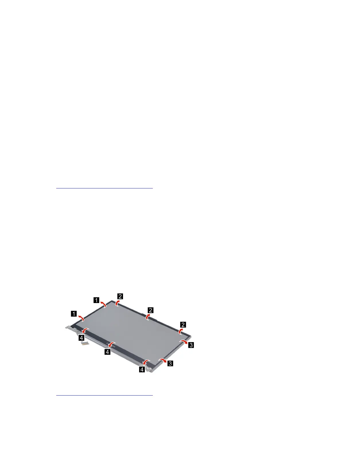
Remove the LCD bezel
Make sure the following FRU (CRU) has been removed.
“Remove the LCD module” on page 45
Step 1. Remove the LCD bezel.
Figure 35. Remove the LCD bezel
Go to https://support.lenovo.com/partslookup to look up the Lenovo part number of the following replacement
part:
LCD bezel
Chapter 4. Removing a FRU or CRU 47
 Loading...