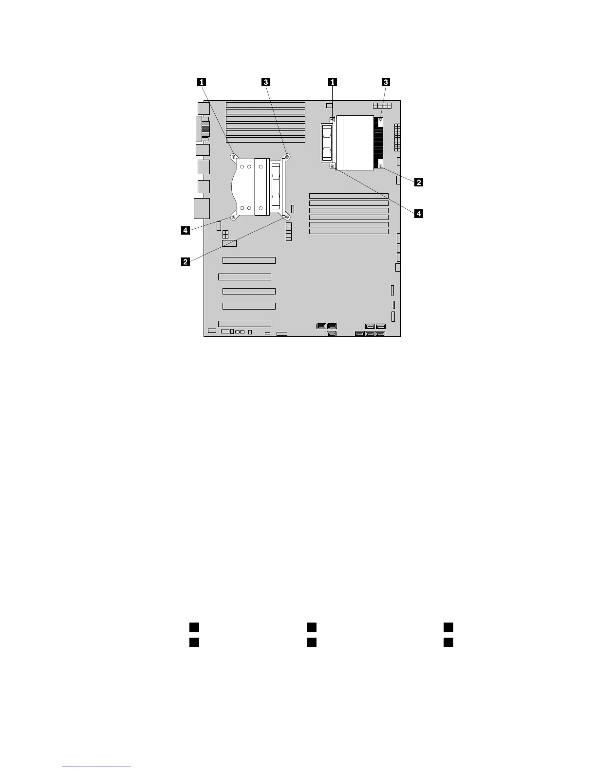
Figure28.Removingtheheatsinkandfanassembly
8.Carefullylifttheheatsinkandfanassemblyoffthesystemboard.
Notes:
a.Youmighthavetogentlytwisttheheatsinkandfanassemblytofreeitfromthemicroprocessor.
b.Donottouchthethermalgreasewhilehandlingtheheatsinkandfanassembly.
9.Removetheplasticcoverfromthebottomofthenewheatsinkandfanassemblytoexposethethermal
grease(thiscoverprotectsthethermalgreasefromcontamination).
Notes:
a.Donotremovetheplasticcoveruntilyouarereadytoinstalltheheatsinkandfanassemblyon
themicroprocessor.
b.Donottouchthethermalgreaseontheheatsinkandfanassembly.
c.Donotputtheheatsinkandfanassemblyanywhereexceptonthemicroprocessoraftertheplastic
coverhasbeenremovedandthethermalgreaseexposed.
10.Positionthenewheatsinkandfanassemblyonthemicroprocessorsothatthefourscrewsarealigned
withtheholesinthesystemboard.
Note:Positionthenewheatsinkandfanassemblysothattheheatsinkandfanassemblycableis
towardthemicroprocessorfanconnectoronthesystemboard.
11.Followthissequencetoinstallthefourscrewstosecurethenewheatsinkandfanassembly:
a.Partiallytightenscrew1,thenfullytightenscrew2,andthenfullytightenscrew1.
b.Partiallytightenscrew3,thenfullytightenscrew4,andthenfullytightenscrew3.
12.Connecttheheatsinkandfanassemblycabletothesystemboard.See“Locatingpartsandconnectors
onthesystemboard”onpage71.
13.Ifyouarereplacingheatsinkandfanassembly2,reinstalltheopticaldrivebracketintothechassis.
14.Reinstalltheopticaldriveintothechassis.See“Replacingtheopticaldrive”onpage88.
92ThinkStationHardwareMaintenanceManual
 Loading...