Fixed power supply model
The rear of the server provides access to several components, including the power supplies, PCIe adapters,
serial port, and Ethernet port.
Note: Depending on the configuration, your server might be slightly different from the image.
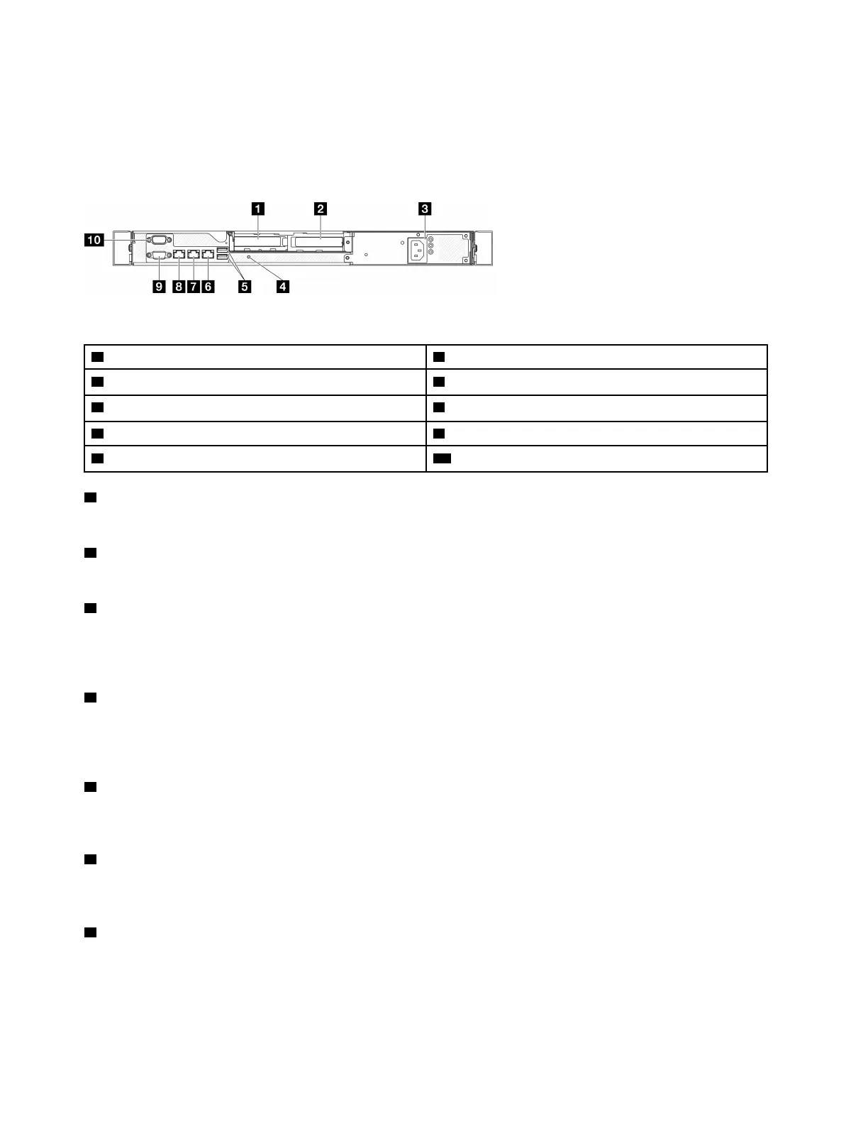
Figure 5. Fixed power supply model rear view
1 PCIe slot 1
6 Ethernet connector 2
2 PCIe slot 2 7 Ethernet connector 1 (shared with XCC network port)
3 Power supply bay
8 XCC system management port (1 GB RJ-45)
4 NMI button
9 VGA connector
5 USB 3.2 Gen 1 (5 Gbps) connectors 10 Serial port
1 PCIe slot 1
Install PCIe adapters into this slot.
2 PCIe slot 2
Install PCIe adapters into this slot.
3 Power supply bay
Install a fixed power supply unit to this bay, connect them to power cords. Make sure the power cords are
connected properly. See “Install the fixed power supply unit” in ThinkSystem SR250 V3 User Guide or
ThinkSystem SR250 V3 Hardware Maintenance Guide.
4 NMI button
Press this button to force a nonmaskable interrupt to the processor. You might have to use a pen or the end
of a straightened paper clip to press the button. You can also use it to force a blue-screen memory dump.
Use this button only when you are directed to do so by Lenovo Support.
5 USB 3.2 Gen 1 (5 Gbps) connectors
The USB 3.2 Gen 1 (5 Gbps) connectors are direct connect interfaces (DCIs) for debugging, which can be
used to attach a USB-compatible device, such as a USB keyboard, USB mouse, or USB storage device.
6 Ethernet connector 2
Attach an Ethernet cable for LAN. Each Ethernet connector has two status LEDs to help you identify the
Ethernet connectivity and activity.
7 Ethernet connector 1 (shared with XCC network port)
Attach an Ethernet cable for LAN. Each Ethernet connector has two status LEDs to help you identify the
Ethernet connectivity and activity. If the LOM adapter is not installed, Ethernet connector 1 can be set as
Lenovo XClarity Controller Network connector. To set Ethernet connector 1 as Lenovo XClarity Controller
Network connector, start Setup Utility and select BMC Settings ➙ Network Settings ➙ Network Settings
Network Interface Port : Shared. Then, click Shared NIC on and select Onboard Port 1.
20
ThinkSystem SR250 V3 System Configuration Guide

 Loading...


