DEUTSCHENGLISHFRANÇAISITALIANOESPAÑOLNEDERLANDS
PORTUGUÊS
SVENSKA
© HAAG-STREIT AG, 3098 Koeniz, Switzerland – HS-Doc. no. 1500.7220055.04100 – 10. Edition / 2015 – 06
NOTE!
• When you use the T-Cone for the rst time with the Lenstar LS 900 biom-
eter, the software will prompt you to calibrate the T‑Cone with the Lenstar
LS 900 biometer. To do so, follow the software wizard and read the soft‑
ware operating instructions (F1 key).
• We recommend performing a test measurement every time the T‑Cone
is tted and removed. The test measurement can be invoked in the soft-
ware’s biometry menu. To do so, follow the software wizard and read the
software operating instructions (F1 key).
4.3.2 Measuring with the optional T-Cone
• Fit the T‑Cone as described in 4.2.1.
• Prior to every measurement procedure, the tip of the T‑Cone should be cleaned with
a lint‑free
cloth soaked in 70% alcohol.
To do so, use a moistened cotton bud or lint‑
free cloth. The cloth or cotton bud must not be so wet that it drips. Ensure that the
T‑Cone is dry after the cleaning. Information on cleaning the T‑Cone can be found un‑
der "Cleaning".
• Retract the Lenstar / T‑Cone completely before positioning the patient in the head rest.
Always start the measuring procedure with the Lenstar / T‑Cone in the position furthest
away from the patient.
• Explain to the patient that he should focus on the red, ashing light (measuring beam)
in the centre of the T‑Cone. The second eye (the one not being measured) can be cov‑
ered with the eye patch on the optional head rest.
• Start the measuring procedure by pressing the button on the joystick and following the
instructions on your PC screen. Detailed information on the measuring procedure can
be found in the operating instructions for the software (F1 key).
NOTE!
Ensure that the Lenstar / T‑Cone is in the position furthest away from
the patient before switching from the rst eye to the second eye. This
ensures that the T‑Cone will not touch with the bridge of the patient’s
nose.
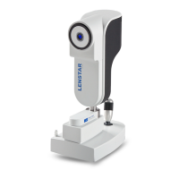
4.3.3 Removing the optional T-Cone
• Hold the T‑Cone by the metal ring and press the locking clip
(17). Now remove the T‑Cone by tilting it off the front ring of
the Lenstar as shown in the image.
• Place the T‑Cone on the base plate of the storage pack‑
aging (19).
• Place the dust cover (14) on the base plate of the storage
packaging (19) to protect the T‑Cone from dust and dirt.
TO
P
17
4.4 Fixation
To obtain usable results, the patient must stare at the red xation light in the mea-
suring lens during measurement. If the patient has dif culty seeing the xation light
with the eye being measured, this can be remedied by xating a remote object with
the other eye.
4.5 Measured variables
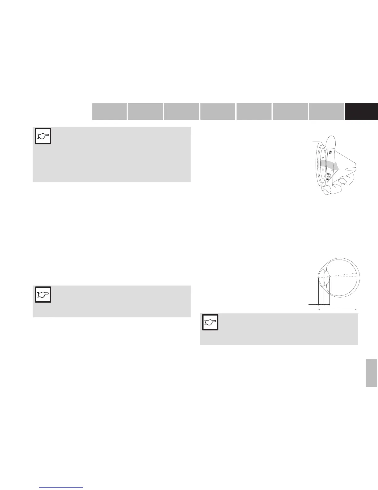
4.5.1 A-Scan
Depending on the patient’s gaze at the xation light, the optical path length of the
visual axis is measured (34).
CCT:
AD:
LT:
AL:
Central corneal thickness
Aqueous depth (back of cornea to front of
lens).
Lens thickness
Axial eye length (front of cornea to the inner
limiting membrane).
A D
A L
C C T L T
34
NOTE!
Since the device measures up to the retinal pigmented epithelium, the
reading displayed is adjusted to the internal limiting membrane, either
automatically, as a function of axial length, or manually, according to
the mode selected. (Manual correction is not available in the USA)
01-IFU_LS900-7220055-04100_eng.indd 11 17.06.2015 10:56:02