DEUTSCHENGLISHFRANÇAISITALIANOESPAÑOLNEDERLANDS
PORTUGUÊS
SVENSKA
© HAAG-STREIT AG, 3098 Koeniz, Switzerland – HS-Doc. no. 1500.7220055.04100 – 10. Edition / 2015 – 06
2.3 Control component (PC)
A commercial PC is used as the control component for the biometer.
WARNING!
The software must be installed by trained personnel in accordance with
the separate installation instructions. For further information, please
contact your HAAG‑STREIT representative.
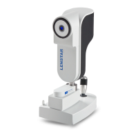
2.4 Instrument table (option)
An adjustable instrument table (option) allows the height of the device to be set at a
comfortable height for the individual patient.
28. Table top
29. Left‑hand drawer (for external medical power supply) / Switch box SB01
30. Right‑hand drawer (empty)
31. Elevator column (mechanical with spring)
32. Stand base with castors
28
29
30
31
32
3. Appliance assembly / installation
WARNING!
The device must be installed by trained personnel in accordance with
the installation instructions provided in the separate service manual.
3.1 Computer connection
WARNING!
For connection to PC, only use the supplied USB cable (2 m)
• Connect the electric power supply cable. Integral mains components work with the
voltages specied under section A.1.1 "Electrical data". It is not necessary to select
the voltage on the device.
• If an instrument table HSM 901 (option) has been supplied, the power supply of the
LS 900 can be connected to the Switchbox SB01 (left drawer). Use the instructions for
use enclosed with the switchbox and the instrument table.
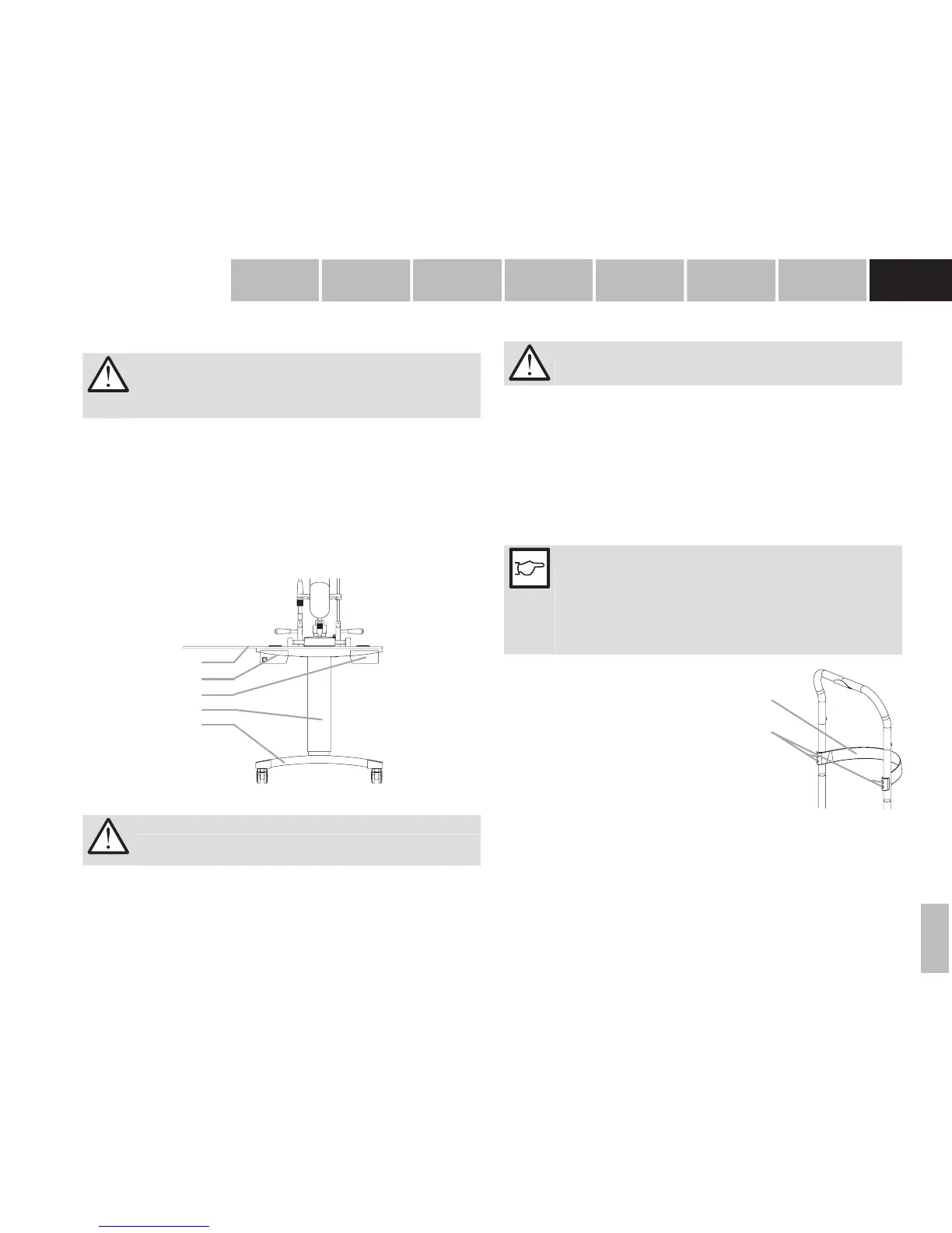
3.2 Installing a short forehead band when using the
optional T-Cone
NOTE!
If the Lenstar LS 900 biometer with the optional T‑Cone topography
add‑on is used on an instrument table with a HAAG‑STREIT head rest
(HS art. no. 7200123), the short forehead band delivered with the op‑
tional T‑Cone must be used on the head rest for better measurability. If
the Lenstar is operated without the optional T‑Cone, the short forehead
band does not need to be replaced with the long one.
33. Phillips screws
34. Forehead band
• Detach the forehead band by removing the four Phil‑
lips screws (34) using a size 1 Phillips screwdriver.
• Remove the forehead band (33).
• Insert the short forehead band (
HS art. no.
1021653
) into the head rest and align the holes with
the holes in the head rest.
• Attach the short forehead band using the four Phil‑
lips screws supplied.