54 Information SET-02
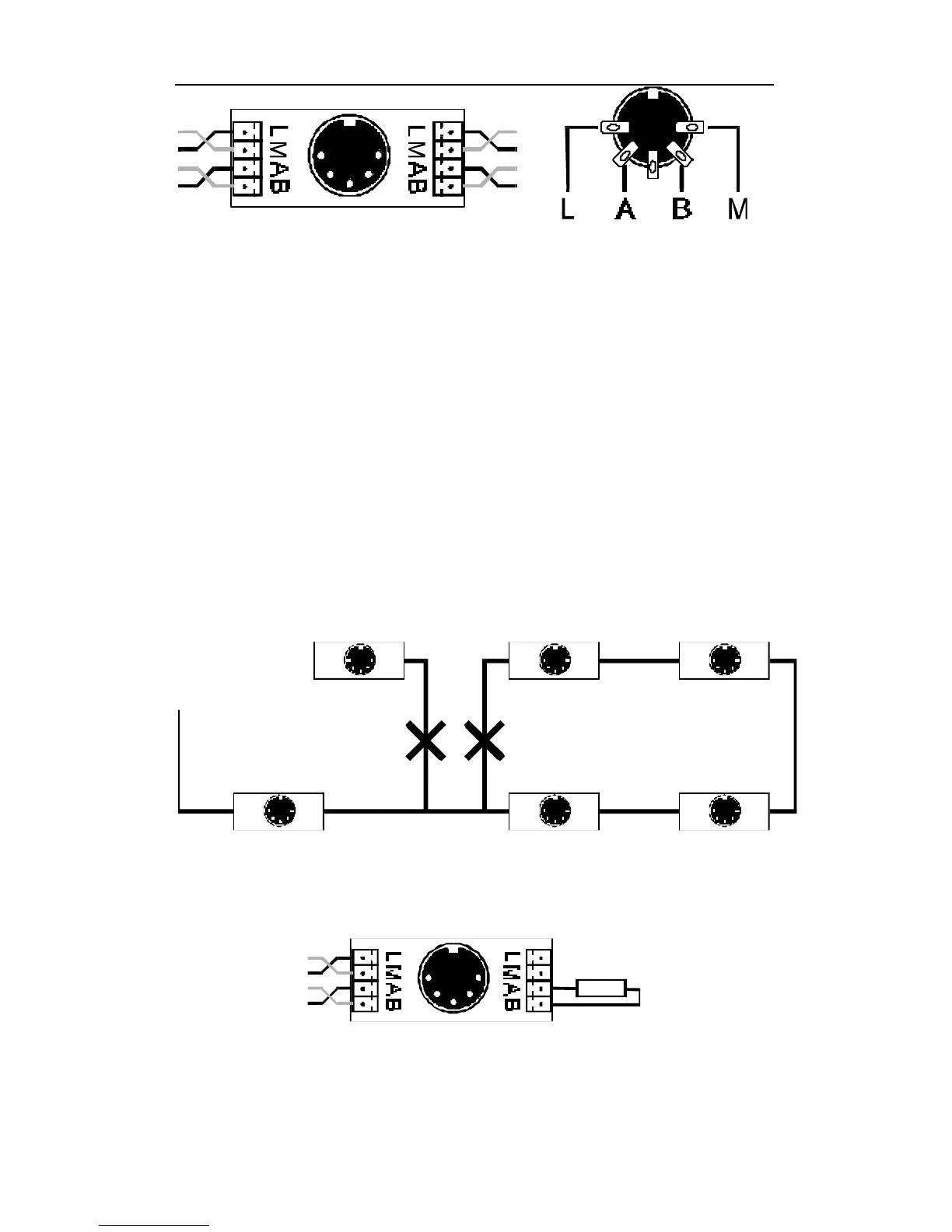
Connection Board LA150 21150 Pin Assignments from solder
side
Make sure that you do not mix up the cables of the terminals
L and M. This could result in a short in the connected input
devices.
The devices exchange information with the command station via the
cables at the terminals A and B. The devices are supplied with
electricity via the terminals L (plus) and M (minus).
The X-Bus wire must be installed so that the line starts at the
Command Station and ends somewhere on your layout. (Daisy
chained from Command Station via intermediate input locations to
the last input location.) Between the start and end you may insert
connecting panels or 5-pin DIN connectors anywhere. You may not
route the wire in a hub-spoke pattern or as a closed loop. Under all
circumstances you must ensure that the wires that are connected
to terminals A and B are twisted.
The ends of the X-Bus Network lines A and B must be connected to
the resistor which is enclosed with the LA152 adapter The resistor
has a value of 120 Ohm.
Terminating the X-Bus with a resistor