13
L
4 Installation
4.1 Installation
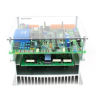
When installing into an enclosure ensure sufficient ventilation. The
ambient temperature must not exceed +45 °C. Install the controller
with the terminals at the top.
External operating elements (e.g. switch, fuses) must not be
arranged close (≤ 250 mm) to the controller 480. If this distance is
not observed, a suitable cover must be provided in order to avoid
accidental contact with the controller board.
4.2 Connection
• The controllers contain electrostatically sensitive components. Prior
to assembly and servicing the personnel must be free of
electrostatic charges. Discharging is possible by touching the PE
fixing screw or another grounded metal part in the control cabinet.
• If you use residual current devices:
− The controllers have an internal mains rectifier. After a short-
circuit to frame a DC fault current may prevent the tripping of
the residual current device. Therefore, take additional
measures like zeroing or use universal current e.l.c.b.
− Observe for the dimensioning of the release current of
e.l.c.b. that capacitive compensating currents of the cable
screens and RFI filters occuring during normal operation
may cause false tripping.
− Note for the use of universal e.l.c.b.:
The preliminary standard prEN50178 (in the past VDE0160)
about the use of universal e.l.c.b. has been decided by the
German committee K226.
The final decision about the use in compliance with the
standard is made by the CENELEC/CS (European
Committee for Electrotechnical Standardization) in Brussels.
Further information on the use of universal current e.l.c.b.
can be obtained from the supplier.
The phase sequence for the connection of the power terminals L1,
L2, L3 is arbitrary.
All cables from and to the controller must be screened. Connect the
screening at both ends, close to the cable ends, to the central PE
connection. When using the supplied set-value potentiometer, the
mechanical screw fixing must have an additional PE connection
and the connections must be insulated and covered.
Caution!
In the operating mode "armature voltage control with I x R
compensation" all control terminals carry mains potential.

 Loading...