Do you have a question about the Lenze 490 Series and is the answer not in the manual?
Details the calculation and values for field voltage UF based on mains voltage.
Explains the method for supplying field voltage using an autotransformer.
Initial setup of trimmers nmax, Vp, and IxR for basic operational adjustment.
Procedure for adjusting the maximum armature current limit of the controller.
Setting procedure for armature voltage feedback with IxR compensation.
Setting procedure for speed control when using tacho feedback.
Adjustment of the noffs trimmer for set value provision and offset correction.
Function of the quick stop switch for decelerating the drive to standstill.
How to release or inhibit the controller using the RFR switch.
Details the function of the controller inhibit switch (RSP).
Application proposal for performing fast inching operation.
Indicates controller readiness and power supply status via LED.
Shows controller inhibit, temperature, or phase errors via LED.
Indicates when the speed controller is operating at its limit.
Signals incorrect rotating field or suppressed firing pulses.
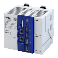
Physical dimensions, layout, and key features of the controller unit.
Details dimensions and part numbers for the required mains chokes.
Power loss values for the current controller, fuses, and mains choke.
| Brand | Lenze |
|---|---|
| Model | 490 Series |
| Category | Controller |
| Language | English |