System bus (CAN) with Ser vo PLC & Drive PLC
General information
2-9
l PLC-Systembus EN 1.1
2.6 Transmitting parameter data
With Lenze devices ”codes” are parameter data.
• Parameter data are, for instance, set when the plant settings are made during commissioning
or when the material for the production machine is changed.
• Parameter data are transmitted as so-called SDOs (
Service Data Objects
) via the system bus
and acknowledged by the recipient, i.e. the transmitter receives a message whether the
transmission was successful.
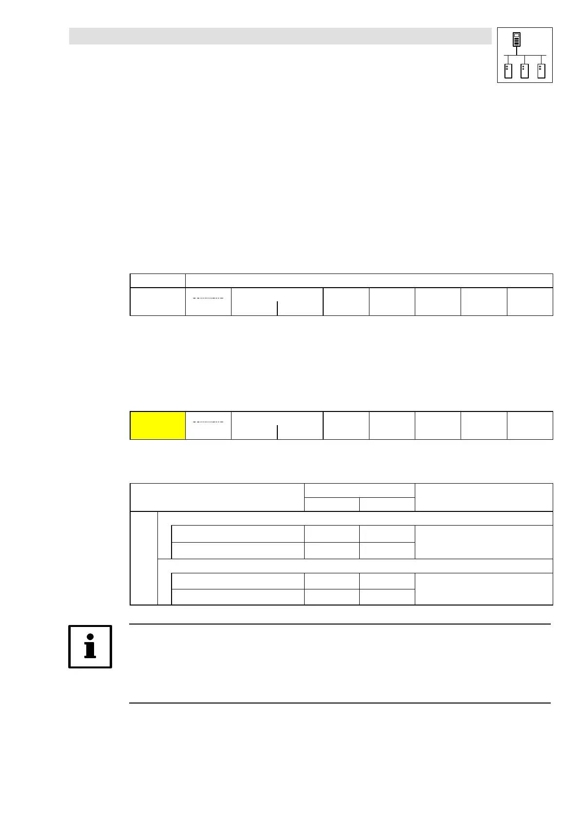
2.6.1 Telegram structure
Structure of the telegram for parameter data:
11 Bit 8-byte user data
Command
Index
ent
er
code
Low-byte High-byte
u
n
e
ata
ata
ata
ata
• In the below sub-sections, the individual telegram components are explained in detail.
• In chapter 2.6.2 you can find an example of writing a parameter. (^ 2-13)
• In chapter 2.6.3 you can find an example of reading a parameter. (^ 2-14)
2.6.1.1 Identifier
Command
Index
ent
er
code
Low-byte High-byte
u
n
e
ata
ata
ata
ata
Two parameter channels are available for parameter data transmission. They are addressed via the
identifier.
Identifier = Basic identifier + node address of the participant
dec hex
SDOs Parameter channel 1
Output (transmit) 1536 600
+ C0350
(CAN)
Input (receive) 1408 580
+
5
+ C2450
(FIF CAN)
Parameter channel 2
Output (transmit) 1600 640
+ C0350
(CAN)
Input (receive) 1472 5C0
+
5
+ C2450
(FIF CAN)
Tip!
There is an offset of 64 between the identifiers for parameter channels 1 and 2:
• Output parameter channel 1 = 1536
• Output parameter channel 2 = 1536 + 64 = 1600