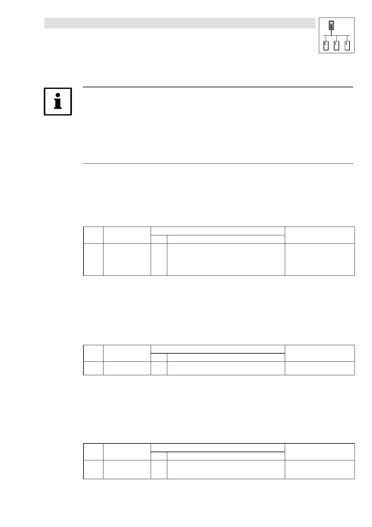
System bus (CAN) with Ser vo PLC & Drive PLC
Configuration
3-1
l PLC-Systembus EN 1.1
3 Configuration (integrated system bus interface)
Tip!
Changes in the CAN baud rate, the CAN addresses and the PDO identifiers are only accepted after
a reset node.
A reset node can be initiated by
• afreshpower-on
• a reset node command through an NMT command (^ 2-5)
• a reset node via C0358 (^ 3-6)
3.1 CAN baud rate
All participants must use the same baud rate for data transmission to enable communication via the
system bus.
• The baud rate is configured via code C0351:
Code LCD
Possible settings
Info
Lenze Choice
C0351 CAN baud rate 0 0 500 kbit/s
1 250 kbit/s
2 125 kbit/s
350kbit/s
4 1000 k bit/s
System bus baud rate
• Save changes with C0003 = 1
• Changes will only become
effective after a reset node!
3.2 CAN boot-up
Unless a higher-level host system controls the system bus initialisation and the status change from
pre-operational
to
operational
, you can select a PLC or a drive controller as a “quasi” master to fulfil
this task.
• Configuration is made via code C0352:
Code LCD
Possible settings
Info
Lenze Choice
C0352 CAN mst 0 0 Boot-up not active
1 Boot-up active
Delay time for system bus initialisation (boot-up)
Some bus participants (e.g. HMIs) need a certain start-up time after power-on before they can
accept NMT commands from the master to switch to
operational
.
You can set a delay time to be observed after power-on before NMT commands are transmitted to
ensure that all bus participants, even the one with the longest start-up time, are really ready to
receive the NMT commands.
• The delay time is configured via code C0356/1:
Code LCD
Possible settings
Info
Lenze Choice
C0356/1 CAN boot-up 3000 0 {1 msec} 65000 Delay time after power-on for
initialisation through the “quasi”
master