Configuration
7-247
SHB9300CRV EN 2.0
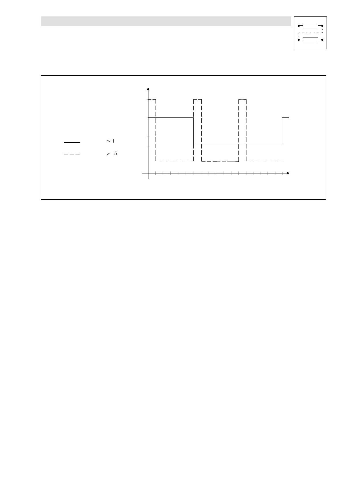
Overcurrent diagram for fault message ”OC5”
200%
150%
100%
70%
10s
60s
120s
180s
Time
Controller output current *
Ixt - diagram
(100% load)
for C0022
$
150 I
rx
70% thermal continuous current
for C0022
150% I
rx
* rated controller current 100%
x depends on the chopper frequency of the inverter
100% thermal continuous current
K35.0151
Fig. 7-193 Max. permissible overcurrent depending on the time
 Loading...