Function library
Positioning control
3.4.8 Homing
3−54
l
EDSVS9332P−EXT DE 2.0
3.4.8.8 Homing modes 8 and 9
Purpose
l Homing in all positioning modes (C1210 = 0, 1, 2).
l Use of touch probe if the index pulse does not appear at the same place in a reproducible
form due to the mechanical constellation. The index signal can also be mechanically shifted
after a motor replacement.
l The touch probe must be situated in direction of movement. The TP must not be assigned
before starting homing.
Directly travel to TP signal
Mode 8: Traversing direction to the positive end of the travel range limit switch
Set C1213 = 8.
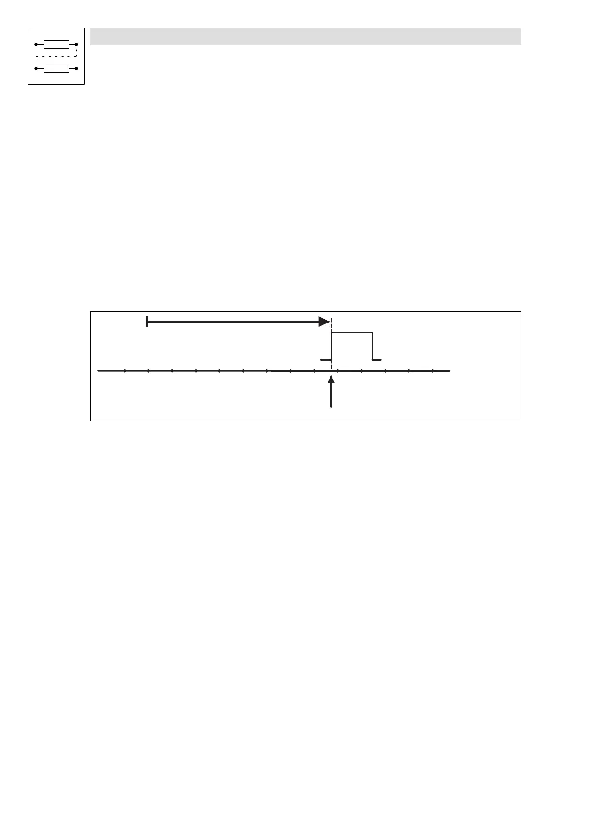
Home position
TP signal
9300pos055
Fig. 3−20 Move to TP signal
The following settings are necessary:
l Select terminal for TP initiator via C1214.
– C1214 = 1 ¢ terminal X5/E1.
– C1214 = 2 ¢ terminal X5/E2.
– C1214 = 3 ¢ terminal X5/E3.
– C1214 = 4 ¢ terminal X5/E4 (This setting is recommended by LENZE).
l Select signal of the TP input via C1215/x.
– C1215/x = 0 ¢ LOW−HIGH edge.
– C1215/x = 1 ¢ HIGH−LOW edge.
Function sequence
l Move to the TP signal with homing speed (C1242) towards positive end of travel range limit
switch.
l The first TP signal determines the reference point.
Mode 9: Traversing direction to negative end of travel range limit switch
Set C1213 = 9.
Function sequence
l As "Traversing direction to positive end of travel range limit switch", but the drive moves
towards the negative end of travel range limit switch.