Function block library
7-60
SHB9300CRV EN 2.0
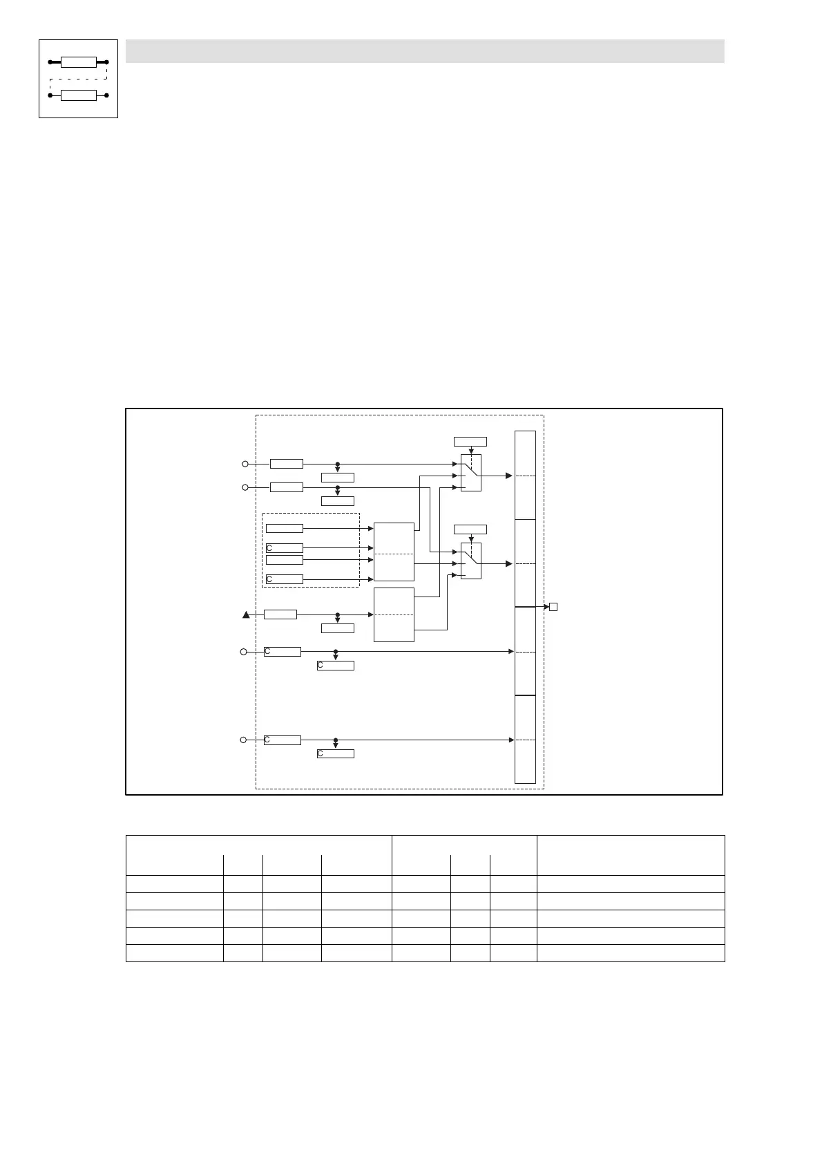
Byte 1, 2, 3 and 4
The meaning of these user data can be selected among different signal types. Depending on the
requirement, up to two analog signals, 32 digital signals of the function block FDO or a phasesignal
can be selected.Mixed forms are also possible.
Byte 5 and 6
Here, the analog signal configured at the input CAN-OUT2.W3 is mapped.
Byte 7 and 8
Here, the analog signal configured at the input CAN-OUT2.W4 is mapped.
CAN-OUT3
The process data object CAN-OUT3 is provided for the event-driven transmission of process data
and for communication among the controllers. Decentralized outputs can also be accessed.
Byte 1,2
Bit 0
Bit 15
Bit 0
Bit 31
B y te 7 ,8
B y te 5 ,6
System bus
term inals
X4
B y te 3 ,4
1
0
2
C 0865/3
1
0
2
C 0864/3
CAN-OUT3.D1
16 Bit
Low W ord
16 Bit
H igh W ord
C 0861/3
16 Bit
Low W ord
16 Bit
H igh W ord
C 0869/3
FDO -0
FDO -15
...
CAN-OUT3.W 1
C 0860/8
CAN-OUT3.W 2
C 0860/9
C 0868/8
C 0868/9
FDO
C 0116/1
C 0116/16
FDO -16
FDO -31
...
C 0116/17
C 0116/32
Bit 0
Bit 15
CAN-OUT3.W 3
CAN-OUT3.W 4
Bit 15
C 0860/10
C 0868/10
C 0868/11
C 0860/11
Fig. 7-49 System bus (CAN-OUT3)
Signal
Source Note
Name Type DIS DIS format CFG List Lenze
CAN-OUT3.W1 a C0868/8 dec [%] C0860/8 1 1000 +100 % = +16384
CAN-OUT3.W2 a C0868/9 dec [%] C0860/9 1 1000 +100 % = +16384
CAN-OUT3.W3 a C0868/10 dec [%] C0860/10 1 1000 +100 % = +16384
CAN-OUT3.W4 a C0868/11 dec [%] C0860/11 1 1000 +100 % = +16384
CAN-OUT3.D1 ph C0869/3 dec [inc] C0861/3 4 1000 1 revolution = 65536
Function
The input signals of this function block are copied to the 8 byte user data of CAN object 3 and laid
on the system bus. The meaning of the user data can be determined very easily with C0864/3 and
C0865/3 and the corresponding configuration code (CFG).
 Loading...