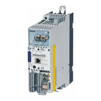
Do you have a question about the Lenze HighLine E94AMHE0074 and is the answer not in the manual?
Guide for installing the L-force drives, covering assembly and setup.
Initial safety warnings and instructions presented in multiple languages.
Essential safety precautions and application guidelines for Lenze controllers.
Guidelines for safe installation, handling, electrical connections, and operation.
Information on safety functions and maintenance requirements for controllers.
Details potential dangers, risks, and protection measures for personnel and devices.
Explains pictographs and signal words used for warnings and important information.
Safety guidelines specific to UL and UR approved installations.
Lists and describes standard device components and LED status indicators.
Outlines the sequential steps for installing the device.
Overview of general specifications, standards, and environmental operating conditions.
Detailed electrical input specifications including voltage, current, and phases.
Detailed electrical output specifications including voltage, current, and phases.
Assignment of installation backplane types with fuses and device sizes.
Physical dimensions and mass of the standard device with installation backplane.
Illustrates the electrical circuit and explains connected components and signals.
Instructions for mounting and wiring the installation backplane.
Step-by-step guide for inserting and removing the standard device.
Guidelines for cable types, shielding, and connection methods.
Details the wiring for the onboard system bus CAN connection.
Information on connecting the 24 V external supply and state bus.
Wiring specifications for analog input and output terminals.
Wiring details for the digital output terminals.
Wiring details for the digital input terminals.
Wiring for diagnostic interfaces, resolvers, and encoders.
Information on connecting Ethernet and CANopen communication modules.
Details the connections for the CANopen communication module.
Configuration of DIP switches for node address and baud rate.
Details the connections for the PROFIBUS communication module.
Setting the bus node address for PROFIBUS modules using DIP switches.
Details on connecting digital frequency and other function modules.
Explains the status indicators for function modules.
Information on different memory module types and their installation.
Details on MM2xx, MM3xx, and MM4xx memory module features.
Configuration of DIP switches for node address and baud rate on memory modules.
Introduction to the SM0 safety module and its function.
Details the SM100 safety module and its "Safe torque off" function.
Information on SM300 safety module, STO, SS1, and critical installation safety.
Setting PROFIsafe address and terminal assignments for SM300.
Details terminal assignments for SM300 module outputs and inputs.
Explains the meaning of display indicators for safety modules.
Lists requirements for preparing the device commissioning process.
| Product series | HighLine |
|---|---|
| Control Type | Vector control |
| Protection Class | IP20 |
| Supply voltage | 400-480 V AC |
| Input Voltage | 3 x 400/480 V AC |
| Communication Interface | CANopen, Profibus |


 Loading...