Do you have a question about the Lenze HighLine E94AMHE0034 and is the answer not in the manual?
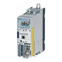
Lists components of the standard device and their design.
Explains LED indicators for operating states.
Lists components of the installation backplane and their design.
Directs users to safety instructions before starting.
Directs users to review technical data.
Instructions for mounting and wiring the backplane.
Steps for installing the standard device into the backplane.
Instructions for wiring the standard device.
Guide for wiring and adjusting device modules.
Covers final tasks after module installation.
Provides general safety and application guidance for controllers.
Safety guidelines for device installation and handling.
Safety notes for electrical connections and EMC.
Safety precautions to be observed during operation.
Information on special safety functions like 'safe torque off'.
Guidelines for routine maintenance and cleaning.
Instructions for proper recycling and disposal of the product.
Details potential residual hazards and protective measures.
Explains pictographs and signal words used in the document.
Specific safety notes for UL/UR certified installations.
Provides general specifications and environmental conditions.
Details input voltage, frequency, and current ratings for different types.
Specifies output voltage, frequency, and current ratings.
Maps device types to backplanes, fuses, and sizes.
Presents physical dimensions and mass for standard devices.
Illustrates a typical wiring example for the drive system.
Explains the process of mounting and wiring the backplane.
Step-by-step guide for mounting the standard device.
Covers wiring procedures and cable design considerations.
Details connections for the onboard CAN system bus.
Explains the 24V supply connection and terminal data.
Describes connections for analog input and output signals.
Details connections for digital output signals.
Explains connections for digital input signals.
Information on the diagnostic/keypad interface.
Wiring details for the resolver connection.
Wiring specifications for encoder connections.
Overview of different communication modules.
Details the Ethernet communication module and its connections.
Information on the CANopen communication module and connections.
Explains DIP switch settings for bus addressing.
Details the PROFIBUS communication module and its connections.
Addresses DIP switch settings for PROFIBUS node addressing.
Overview of function modules.
Details the digital frequency function module and connections.
Introduces memory modules and their types.
Details the MM1xx memory module equipment.
Describes MM2xx, MM3xx, and MM4xx memory module types.
Overview of available safety modules.
Details the SM0 safety module's function.
Describes the SM100 safety module and its functions.
Details the SM300 safety module and its functions.
Lists connections for the SM300 module.
Explains PROFIsafe addressing via DIP switch for SM300.
Details terminal assignments for SM300 module connections.
Explains the status displays for safety modules.
Lists requirements for commissioning the device.


 Loading...