Operating instructions i550 motec frequency inverter | 11
© 03/2022 · EN · www.Lenze.com
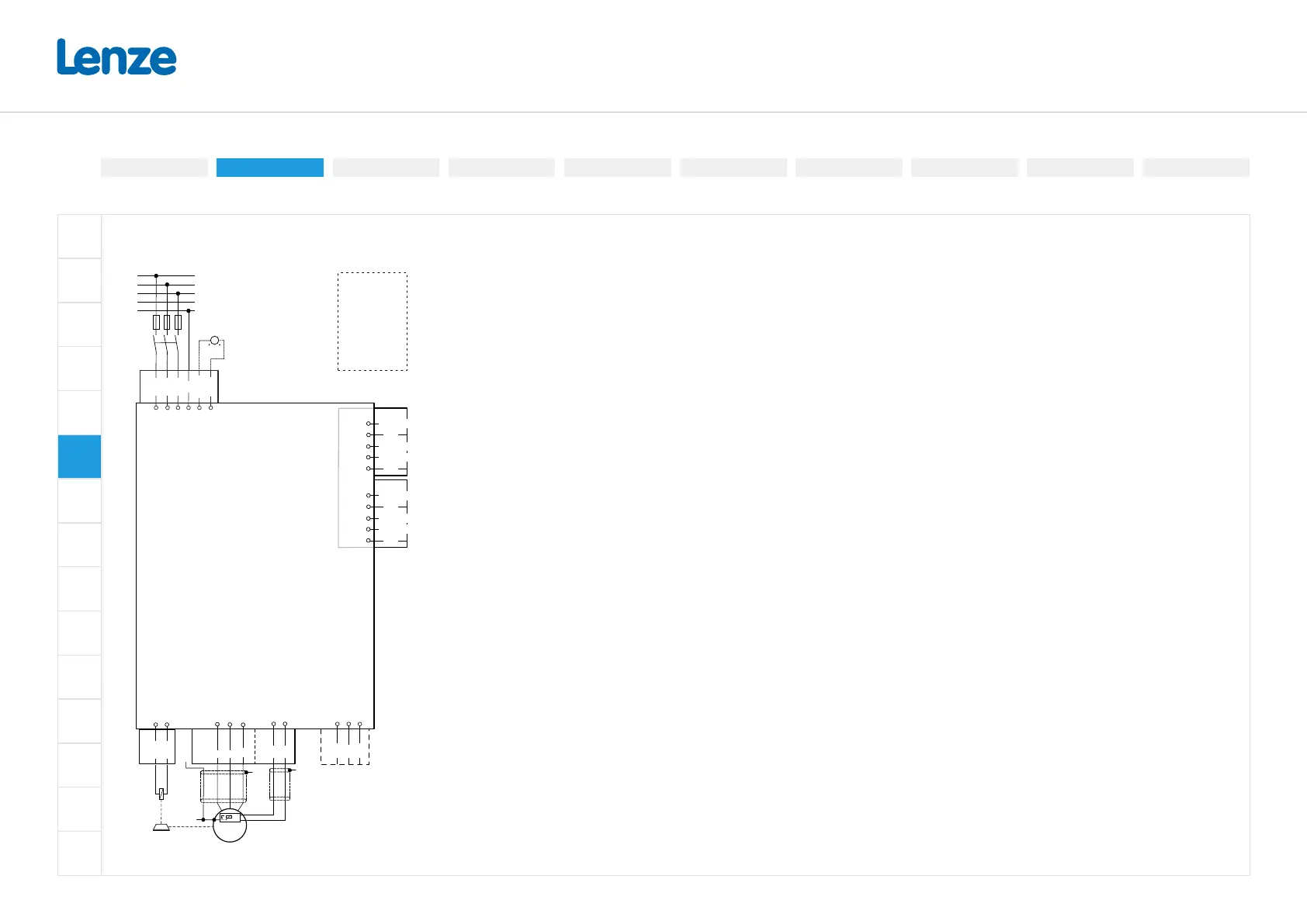
Connection diagram
The connection diagram is considered exemplary for all voltage and power classes.
F1
…
F3
L2.1
L3.1
GND
24E.1
PE
L1.1
X100.1
PE
N
L3
L2
L1
3 x 400V
3 x 480V
SIB
GS
SIA
X1
n.c.
DI3| DO2|C/Q(2)
GND| L-(2)
DI4
24V| L+(2)
X3.2
n.c.
DI1| DO1|C/Q(1)
GND| L-(1)
DI2
24V |L+(1)
X3.1
Applicaon-I/O
Standard-I/O
"
M
3~
+
J
J
U
W
V
X105
+
T1
T2
"
BD2
BD1
X105
(X109)
EtherCAT
EtherNet/IP
Modbus TCP
PROFINET
X39X
USB
X16
DC 24 ... 48 V SELV/PELV
(-20 % … +4 %)
EMC-compliant installation
The drive system of inverter and drive comply with the EMC Directive 2014/30/EU if they are
installed according to the specications of CE-typical drive systems. These guidelines should
also be followed in installations requiring FCC Part 15 or ICES 001 compliance. The structure
at the installation location must support the EMC-compliant installation with shielded motor
cables.
• Please use suciently conductive shield connections.
• Connect the housing with shielding eect to the grounded mounting plate with a surface as
large as possible, e.g. of inverters and RFI lters.
• Use central earthing points.
Mains connection with multiple devices
Several inverters in close proximity can be connected to the mains using the integrated
Han-Q4/2 connectors. The mains cables are looped through from one inverter to the next via
the Han-Q4/2 connector.
Electrical installation
3-phase | 480 V3-phase | 230/240V
3-phase | 400 V
Control connections
Connection diagram
Preparation
Networks
Functional safety
Safe torque o (STO)
PTC input

 Loading...


