EasyManua.ls Logo

Lenze I55AE137 - User Manual

Lenze I55AE137
48 pages
Print Icon
To Next Page IconTo Next Page
Loading...
Operating instructions i550 cabinet frequency inverter | 1
© 11/2021 · EN · www.Lenze.com
Contents
i550 cabinet frequency inverter
0.25 ... 132 kW
Operating instructions

Questions and Answers

  • A
    Alexander BowenAug 17, 2025
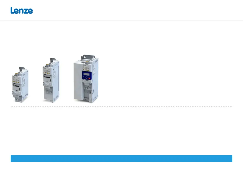
    How to fix continuous overcurrent inside Lenze I55AE137?
    • H
      Heather RasmussenAug 17, 2025
      To resolve continuous overcurrent inside the Lenze Inverter: * Check the motor and wiring for any short circuits. * Inspect the brake resistor and its wiring. * Verify the motor circuit connection (delta or star). * Confirm the correct setting of the motor data.
  • J
    jeffreysmithAug 20, 2025
    What to do if there is DC bus overvoltage in Lenze I55AE137 Inverter?
    • C
      christophershahAug 20, 2025
      If you're experiencing DC bus overvoltage in your Lenze Inverter, take these steps: * Reduce the dynamic performance of the load profile. * Check the mains voltage. * Verify the settings for the brake energy management. * Connect a brake resistor to the power unit and activate the integrated brake chopper by setting P706.01 to 0.
  • T
    Timothy RoblesAug 23, 2025
    Why does Lenze I55AE137 Inverter show a mains phase fault?
    • C
      Casey ButlerAug 23, 2025
      A mains phase fault in your Lenze Inverter can be caused by issues with the power supply. Check the mains connection wiring and inspect the fuses to ensure they are working correctly.
  • R
    Robert HillAug 26, 2025
    How to troubleshoot overtemperature fault in Lenze I55AE137 Inverter?
    • M
      Mark CostaAug 26, 2025
      To troubleshoot an overtemperature fault in your Lenze Inverter: * Check the mains voltage. * Ensure sufficient cooling by monitoring the heatsink temperature (P117.01). * Clean the fan and ventilation slots or replace the fan if needed. * Reduce the switching frequency (P305.00).
  • E
    elijahsanfordAug 28, 2025
    What causes high device utilization on Lenze I55AE137?
    • J
      Johnny HillAug 28, 2025
      High device utilization (Ixt) on your Lenze Inverter can occur due to several reasons. Check the drive dimensions. Reduce the maximum overload current of the inverter (P324.00). If you have high mass inertias, reduce the maximum overload current of the inverter (P324.00) to 150 %.
  • J
    Jonathan LambertAug 30, 2025
    How to fix short circuit on motor side of Lenze Inverter?
    • J
      John RiveraAug 31, 2025
      To address a short circuit or earth leakage on the motor side of your Lenze Inverter: * Inspect the motor cable. * Consider the length of the motor cable. * Use a shorter or lower-capacitance motor cable.
  • J
    Jennifer ZamoraSep 2, 2025
    What to do if Lenze Inverter shows i²*t overload?
    • M
      Mark WatkinsSep 2, 2025
      If your Lenze Inverter is showing an i²*t overload (thermal state), consider the following: * Verify the drive dimensions. * Check the machine/driven mechanics for excessive load. * Confirm the correct setting of the motor data. * Reduce values for slip compensation (P315.01, P315.02) and oscillation damping (P318.01, P318.02).
  • A
    Ashley JacobsSep 5, 2025
    Why is my Lenze I55AE137 motor overheating?
    • D
      Dennis SmithSep 5, 2025
      If your Lenze Inverter motor is overheating: * Check the drive dimensions. * Check the motor thermal sensor and wiring (terminals X109/T1 and X109/T2).
  • D
    Dennis CookSep 8, 2025
    How to resolve DC bus undervoltage in Lenze Inverter?
    • D
      Denise HawkinsSep 8, 2025
      To resolve DC bus undervoltage in your Lenze Inverter: * Check the mains voltage. * Check the fuses. * Check the DC bus voltage (P105.00). * Check the mains settings.
  • K
    Katherine AdkinsSep 12, 2025
    What does '24 V supply critical' mean on Lenze I55AE137 Inverter?
    • T
      timothy59Sep 12, 2025
      If your Lenze Inverter displays '24 V supply critical': * Check the optional external 24 V voltage supply (terminal X3/24E), if connected. * Check the mains voltage.

Summary

Safety, Application, and Regulatory Compliance

Safety Instructions and Application

Covers safe usage, application directives, and protection measures.

Product Identification and Specifications

Product Identification Codes

Explains the coding system for identifying product variants.

Product Variants and Ratings

Details product types, power ratings, voltage, and safety functions.

Safety Instruction Conventions

Safety Hazard Levels

Defines DANGER, WARNING, CAUTION, and NOTE levels for safety instructions.

Basic Safety Instructions

Core Safety Guidelines

Essential safety rules for operating the inverter to prevent injury.

Functional Safety and Device Protection

Information on safety functions and device protection measures.

Residual Hazards and Protective Measures

Electrical Hazards and Precautions

Highlights electrical dangers and necessary protective measures.

Device Protection and Motor Safety

Covers protection against hazards and motor operation safety.

Technical Data and Standards

Approvals and Market Compliance

Lists market approvals and certifications for the inverter.

Inverter Dimensions and Assembly

Dimensional Data Table

Provides detailed dimensions for different inverter models.

Connection Diagrams and EMC Compliance

General Connection Diagram

Provides an exemplary wiring diagram for all voltage and power classes.

EMC-Compliant Installation Guidelines

Guidelines for ensuring EMC-compliant installation of the drive system.

1-Phase 120 V Connection Data

Terminal Data for 120 V Models

Specifies terminal connections and cable cross-sections for 120V models.

Rated Data and Fusing for 120 V Models

Lists rated electrical data, fusing, and circuit breaker information.

1-Phase 230;240 V Connection Data

Terminal Data for 230;240 V Models

Specifies terminal connections and cable cross-sections for 230/240V models.

3-Phase 230;240 V Connection Data

3-Phase 400 V Connection Data

3-Phase 400 V High Power Connection Data

3-Phase 480 V Connection Data

3-Phase 480 V High Power Connection Data

Brake Resistor Connection

Control Terminals (X3)

Relay Output (X9)

PTC Input (X109)

Network Connections and Configuration

Network Protocol Setup

Configuration details for CANopen, Modbus RTU, PROFIBUS, EtherCAT, etc.

Functional Safety Considerations

Uncontrolled Start-up Hazards

Details risks associated with uncontrolled start-up and installation requirements.

Safe Torque Off (STO) Function

STO Safety Requirements

Highlights critical safety requirements for the STO function.

Initial Commissioning Steps

Commissioning Hazards and Precautions

Warns of hazards during commissioning and outlines precautions.

Commissioning Notes and Tools

Dangerous Motor Movements

Warns about unexpected motor movements due to incorrect settings.

Keypad Module Operation

Keypad Control Modes

Terminal Control Quick Commissioning

Parameter Overview and Groups

Basic Setting Parameters

Motor Control Parameters

Motor Nameplate Data Entry

Input of motor data like rated torque, frequency, power, and voltage.

Motor Identification and Calibration

Automatic identification and calibration of motor data.

Troubleshooting: Error Messages

Resetting Errors

Describes methods for resetting errors via keypad or terminal control.

Troubleshooting: Error Codes (Part 1)

Trouble Error Codes

Lists trouble error codes, their descriptions, remedies, and blocking times.

Troubleshooting: Error Codes (Part 2)

Warning and Other Error Codes

Lists warning error codes, their descriptions, remedies, and blocking times.

Troubleshooting: LED Status Indicators

Meaning of RDY and ERR LEDs

Explains the states indicated by the blue 'RDY' and red 'ERR' LEDs.

Lenze I55AE137 Specifications

General IconGeneral
BrandLenze
ModelI55AE137
CategoryInverter
LanguageEnglish

Related product manuals