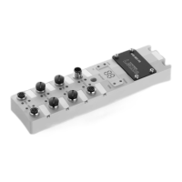
How to fix error E80 on Leuze electronic Controller?
- CCarl CampbellSep 3, 2025
Error E80 on the Leuze electronic Controller indicates an invalid operating mode. Check the configuration of the operating mode and restart.

How to fix error E80 on Leuze electronic Controller?
Error E80 on the Leuze electronic Controller indicates an invalid operating mode. Check the configuration of the operating mode and restart.
What to do if Leuze electronic MSI-MD-FBX shows error E87?
Error E87 on the Leuze electronic Controller means the operating mode has changed. Check the configuration of the operating mode and restart the device.
| Brand | Leuze electronic |
|---|---|
| Model | MSI-MD-FBX |
| Category | Controller |
| Language | English |
Checklists serve as a reference for testing requirements, but do not replace machine testing.
Instructions on how to download diagnostic software from the Leuze website.
Explains warning symbols, signal words, and other symbols used in the manual.
Defines the proper application and outlines improper uses of the safety relay.
Outlines the required qualifications and expertise for handling the safety relay.
Clarifies the safety responsibilities of manufacturers and operators.
Details the physical components and layout of the muting controller with labeled diagrams.
Explains the function of various LEDs and the 7-segment display on the controller.
Describes the types of connectors and sockets used for wiring.
Explains the operation of timing controlled 2-sensor muting.
Details the timing controlled muting function with an external enable signal.
Describes how to override muting and restart the system after interruptions.
Explains the procedure for resetting the muting controller after an error.
Explains how the system restarts after a protective field violation.
Describes the RES LED indication and the acknowledgment/reset process.
Illustrates an application of access guarding using timing controlled muting.
Provides instructions on how to mount the muting controller.
Details the process of mounting the controller within a UDC device column.
Describes mounting the controller on the side or rear of a UDC device column.
Explains how to mount the controller directly onto the machine system using M4 screws.
Provides guidelines for positioning muting sensors for correct operation.
General guidelines for selecting and mounting muting sensors.
Information on choosing and connecting suitable optoelectronic muting sensors.
Specifies the required minimum distance between sensors and the protective field.
Details typical arrangements for muting sensors in 2-sensor muting applications.
Describes an alternative arrangement using diffuse sensors.
Explains the required height for muting sensor light beams.
Lists the connections available on the muting controller for various components.
Details the pin configuration for the machine interface connection.
Describes the pinout for connecting the safety sensor.
Details the pin configuration for the acknowledgment unit.
Explains the pinout for connecting an external muting indicator.
Specifies the pinout for the muting sensor connections.
Provides a circuit diagram example for timing controlled 2-sensor muting.
Circuit diagram for timing controlled 2-sensor muting setup.
Introduces the DIP switch blocks used for configuring the muting controller.
Explains how to set the operating mode using DIP switch blocks.
Outlines testing procedures before initial commissioning and after changes.
Details the periodic testing requirements by qualified personnel.
Describes daily or shift-based checks by the operator.
Provides a checklist for operators to perform periodic testing.
Instructions for cleaning the muting controller.
Information regarding maintenance and repairs.
Guidance on the proper disposal of the electronic component.
General steps to take when the muting controller experiences a fault.
Explains error codes displayed on the 7-segment display and their remedies.
Lists general technical specifications and safety-relevant data.
Shows dimensional drawings of the muting controller.
Provides dimensional drawings for mounting plates.
Lists part numbers and designations for the muting controller.
Details connection cables for the muting controller.
Details interconnection cables for safety sensors.
Lists display and confirmation units.
Lists mounting plates and brackets for the muting controller.
Information on LED muting indicators.