EasyManua.ls Logo

LevelOne FCS-1150 - Page 13

LevelOne FCS-1150
30 pages
Print Icon
To Next Page IconTo Next Page
To Previous Page IconTo Previous Page
Loading...
Hardware Manual
13
The table below shows the DI/DO connection specifications:
Device
DI
Connection design
TTL - compatible logic levels
Voltage
To trigger (low)
Logic level 0: 0V ~ 0.4V
Normal (high)
Logic level 1: 3.1V ~ 30V
Current
10mA ~ 100mA
DO
Connection design
Transistor (Open Collector)
Voltage & Current
< 24V DC, < 50mA
Typical Connection
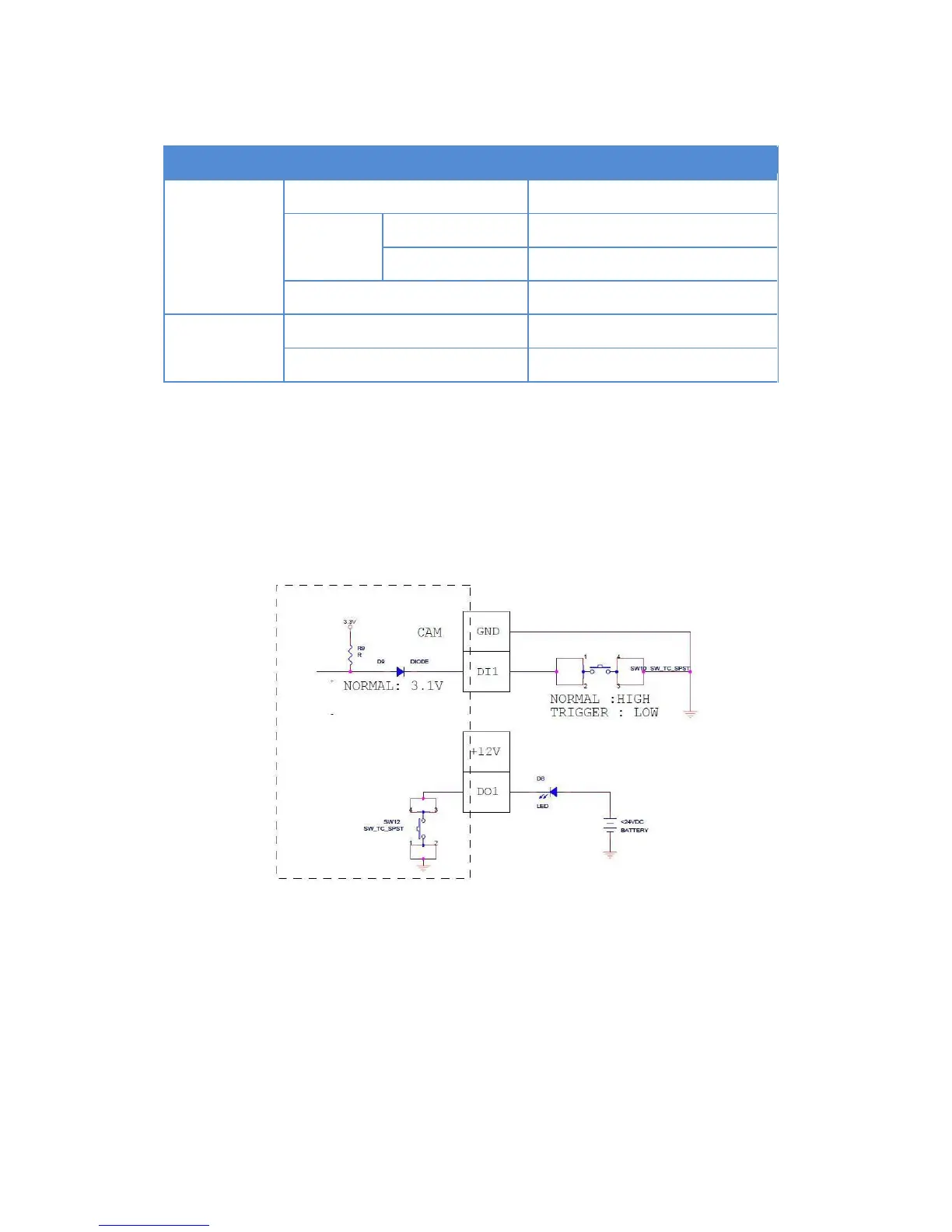
Based on these specifications, if the DI device has a voltage of 0V ~ 30V or the DO device has a
voltage of < 24V (< 50mA), then the camera can supply internal power to these devices and there
is no need to connect the DI/DO device to an external power source.
Use the DIO GND and DI pins to connect a DI device and use the DIO PW and DO pins to
connect a DO device. See wiring scheme below:

Related product manuals