12
4.1.2 USB Connection (Power and Communications)
1. Connect the VerifEye
®
meter to a USB port on your computer to provide
both power and communications.
a. If equipped, the LCD display is the most visible indication of a
running meter.
b. For meters without a display, a green ashing LED on the circuit board
indicates that the VerifEye
®
meter booted up and is running.
CAUTION: The VerifEye
®
meter draws 450 mA from the USB port. Be sure
the USB host is industry standard; otherwise, overloading may occur. If the
meter fails to power or ickers when powering over USB, you must use an
alternate conguration for power.
2. Launch the Power Meter Viewer Utilities application and select
[CONNECT OVER USB] in the pop-up window.
The meter starts to communicate.
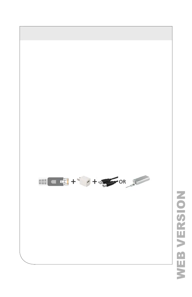
4.1.3 Ethernet Network Connections
To congure the meter over Ethernet requires a secondary power connection.
The meter does not support Power Over Ethernet (POE). If the meter is
already installed within the buildings electrical network, closing the AC
breaker (or approved disconnect) turns ON the meter through the meter’s
internal power supply.
NOTES:
• If a computer’s USB port cannot provide 500 mA of current, you can use an
AC/USB charger or a USB battery as a power source for
Ethernet communications.
• Both the Network Scan and Connect Over Ethernet to IP options require
that a valid network connection exists between the VerifEye® meter and
conguration PC.
4.1.4 Dynamic Host Conguration Protocol (DHCP):
VerifEye
®
meters ship in the DHCP mode to prevent IP conicts with other
equipment. The meter expects to receive an IP address from a DHCP service
provided by a router, Layer 3 switch, or a server providing DHCP service.
Therefore, if the VerifEye
®
meter and the host PC request an IP address from
the same DHCP service provider, they can communicate. When the VerifEye
®
meter powers up, the IP address is shown on the LCD display (if equipped),
or can be found using the Network Scan function.
4 METER CONFIGURATION
 Loading...