Stations need to be given an unique address between
1 and 127. If a station address is set to Zero it will not
participate on the network. You use the address
switch to set both the association to the master station
as well as the IR stations unique address.
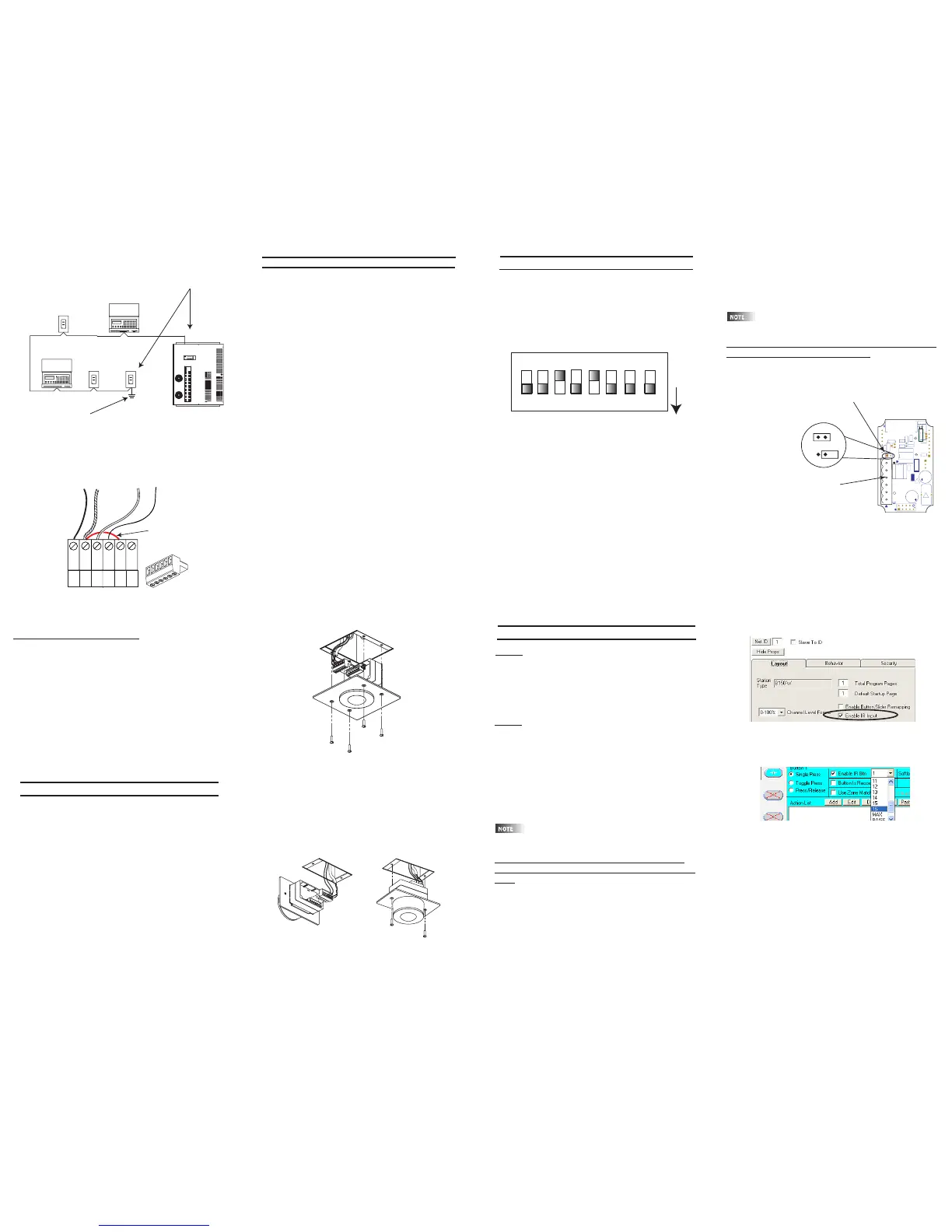
The switch is set to the binary representation of the ID
number. The binary 1’s column is left-most (lever
labeled “1”).
The switch levers are numbered 1-8, these represent
the following:
Lever=Value
1=1 2=2
3=4 4=8
5=16 6=32
7=64 8= Not Used
Add the value of each lever in the “ON” position to
determine the ID number (decimal form).
For example:
To set the address to 39, the following switches need
to be in the “ON” position:
1, 2,3,6 = 1+2+4+32=39
Station Addressing
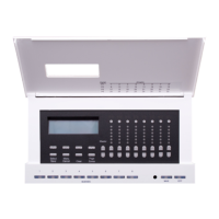
Testing the Wiring
To assure problem-free start-up, it is important to check
the system wiring, prior to hooking up any control sta-
tions, for proper connections, shorts and opens.
The following procedure is recommended:
Step 1: Test the following wire pairs for shorts at each
station location, using an ohmmeter or other continuity
tester.
1-2 Open
2-3 Open
3-4 Open
Step 2: Repair any short circuits before continuing.
Step 3: Install wire jumpers, one pair at a time (not
supplied) to the Luma-Net Connector on either end of
the cable run between pins 1-2, then 2-3, then 3-4.
Step4: Retest each of the following wire pairs at each
connector:
1-2 Short
2-3 Short
3-4 Short
Step 5: Make any necessary repairs and remove wire
jumpers before continuing.
14
Installation
7
8 9
Figure: install of flush mount unit
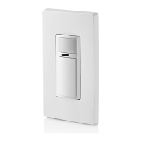
Surface Mount Units:
1. Plug the Luma-Net connector into the back of the
surface mount unit as shown in the figure below.
2. Gently push the wire and assembly into the desired 1
gang electrical box.
3. Use the 2 6-32 screws provided to secure the unit to
the electrical box in the ceiling.
Figure: install of surface mount unit
You must associate the IR station with a Master Station,
either a D4200 LCD station or a D8000 station, in a simi-
lar fashion to the D4200 Entry Stations.
Multiple IR stations of various types can be
slaved to a single master station.
T
o set the remote identification number, and slave it
to a master D4200 or D8000 station:
1. With the station unplugged, set the IR station’s DIP
switches to the address of the master station that it is to
be slaved with.
2. Move the small programming jumper, adjacent to the
Luma-Net connector, so it is plugged onto both pins on
the circuit board.
3. Power up the station by plugging it back in. The red
LED above the jumper will stay lit until the programming
is complete (the D8000 version will flash 3 times).
4. Once the LED goes out, unplug the Luma-Net con-
nector.
D4200:
There is no additional programming that needs to be
done. The D4200 LCD will respond to the hand held
IR units out of the box. If it does not work, double
check the D4200 LCD station to see if the IR port is
turned on. Refer to the units User Guide for details.
D8000:
The IR station is programmed to work out of the box
on a 1 for 1 line up of buttons. This works well for
most station types except the LCD. In this case, it is
recommended that you change the button mapping of
the IR station. You can either create the file in
LumaEdit or use the enclosed CD rom with the ldt file
for an IR station slaved to a generic LCD station.
Treat the IR station just like a 15 button entry station,
that has been slaved to another D8000 station.
In a D8000 system, the IR station does not
have to be slaved to another station
T
o specify a button to listen to a specific command
from a Hand Held remote other than default program
-
ming:
1. Open a 15 Button station in LumaEdit
2. Set the Network ID for the IR station.
3. Set the ID of the station it will be slaved to.
4. Click on the Enable IR button in the Station
Properties Section under Layout.
12 13
Setting the Address Con’t:
5. Remove the programming jumper and replace it so
that it is on only one pin.
6. With the station still unplugged, set the DIP switches
to the desired ID number for this particular remote station
(every station on the network must have its own unique
station number between 1-127).
7. Power up the station by plugging it back in, and it
should be ready to operate normally. When the station
first powers up under operating conditions, the back Red
LED flashes rapidly until the Luma-Net® network
becomes stable/operational.
Programming/Operation
10
Flush Mount Units:
1. Plug the Luma-Net connector into the back of the
flush mount unit as shown in the figure.
2. Gently push the wire aside and install the unit into the
desired 2 gang switch box.
3. Use the 4 6-32 screws provided to secure the unit to
the switch box.
11
1. Click on the button you wish to program. The button
properties box will open.
2. Click on the check box next to “Enable IR Button”
3. From the pull down box to the right, click on the num-
ber/name on the hand held remote that you want this
button to respond to.
4. Repeat Steps 1-3 for every button you wish to
respond to an IR input.
5. Once you have completed the rest of the program-
ming, save the file and write the program to the IR sta-
tion.
6. You are ready for normal operation.
 Loading...