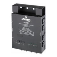
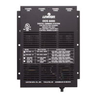
NSI DS8/DS12 MODULAR DIGITAL DIMMING SYSTEM
Software Revision 1.1x, 8/24/99
- 5 -
________________________________________________________________
Control Wiring
DMX-512: Input = 5 pin XLR-M Pin# Signal
Through Output = 5 pin XLR-F 1 DGND
2 DATA -
Recommended 3 DATA +
Control Wire: 4 THROUGH
Belden 9729 or 9829 5 THROUGH
Microplex: Input = 3 pin XLR-M Pin# Signal
(MPX) Through Output = 3 pin XLR-F 1 Analog COM
2 +14.4VDC Power
Recommended 3 DATA
Control Wire:
Belden 8760 or 9460
0-10VDC: Input = 15 pin M D-Sub Pin# Signal
Analog 1 Channel 1
Recommended 2 Channel 2
Control Wire: 3 Channel 3
Alpha 1896 4 Channel 4
5 Channel 5
6 Channel 6
7 Channel 7
8 Channel 8
9 Channel 9
10 Channel 10
11 Channel 11
12 Channel 12
13 T/C (Snapshot)
14 +14.4VDC Power
15 Analog COM
Luma-Net Input = 6 pin pluggable terminal block Pin# Signal
Orientation: looking at back of pack, 1 (far right) REM +
with grooved surface on bottom. 2 REM -
3 DGND
Recommended 4 +14.4VDC Power
Control Wire: 5 N/C
Alpha 1898 6 (far left) N/C
IMPORTANT NOTE: Do not route low voltage control wires parallel to or in the same conduit as high voltage
power wires as the control system may exhibit erratic control performance. (like flickering)
 Loading...