▪ The cross-section of the exhaust line must at least match the inside
diameter of the connections.
▪ When pumping vapours, we recommend connecting a condensate
separator at the exhaust. The exhaust lines should be laid so that they
drop down and away
, thereby preventing condensate from owing
back into the pump.
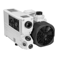
5.4 Removal of pump cover
In order to access the electrical terminals, the purge gas or gas ballast
connections the pump cover has to be removed. To do the pump
maintenance, remove only the front cover of the pump.
To remove the pump cover, do the following steps:
1. Allow the pump to cool down in order to avoid receiving burns from
hot surfaces underneath the cover.
2. Disconnect the inlet ange from the vacuum system.
3. Remove the four side screws of front pump cover. Figure: Remove
the cover.
4. Slide the front cover by hand and remove from the pump.
5. Remove the four side screws of back pump cover.
6. Slide the back cover by hand and remove from the pump.
Figure 4. Remove the cover
1. Front cover 2. Back cover1. Front cover 2. Back cover
5.5 Electrical connection
The pump is supplied with three-phase motor but without accessories for
electrical connection. They must be connected with the appr
opriate cable,
and a suitable motor protection switch.
The pump cover must be removed to connect the motor cable.
Set the switch in accordance with the rating on the pump nameplate.
Please observe the diagram inside the motor junction box.
300766038_002_C3 - 09/2021 - © Leybold
16
Installation