11
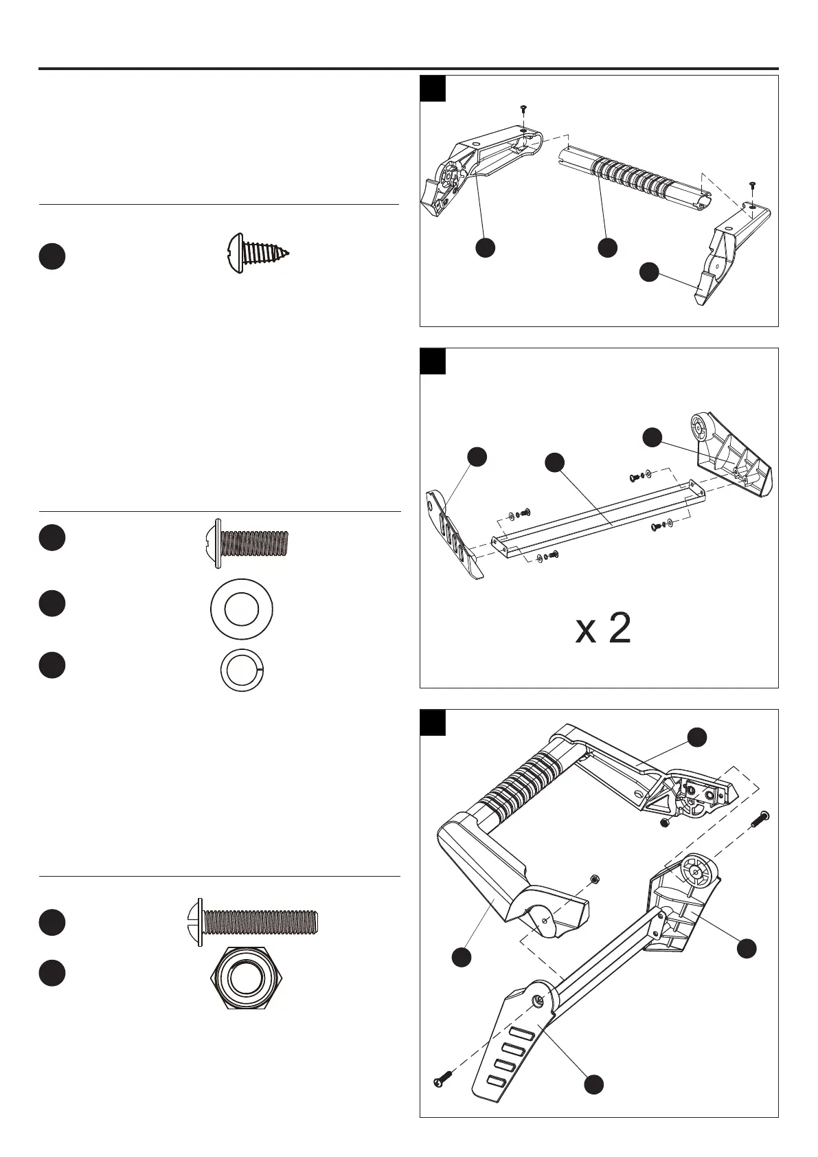
Step 5: Attach Left Handle Assembly onto Left
Leg Assembly
Align the holes in the handle support A (S),
handle support B (U), leg A (V), leg B (X). Then
put them together with four M6 x 25 screws (FF),
four M6 nuts (HH).
Hardware Used
Step 3: Assemble Left Handle
Align the holes in the side handle (T), handle
support A (S) and handle support B (U). Then put
them together with two ST4.2 x 12 screws (EE).
Hardware Used
ASSEMBLY INSTRUCTIONS
Step 4: Assemble Legs
Align the holes in the leg A (V), leg B (X) and leg
brace (W). Then put them together with four
M6 x 12 screws (DD), four Ø6 washers (KK) and
four Ø6 lock washers (NN). Assemble the other
legs in the same way.
Hardware Used
M6
Nut
x 2
M6 x 25
Screw
x 2
ST4.2 x 12
Screw
x 2
M6 x 12
Screw
x 8
Ø6
Lock
Washer
x 8
Ø6
Washer
x 8
EE
DD
KK
NN
FF
HH
3
4
5
U
V
U
S
X
V
W
X
T
S