12
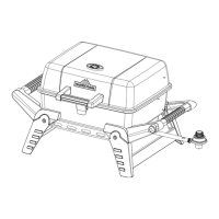
Step 6: Attach Right Handle Assembly onto
Right Leg Assembly
Align the holes in the handle support A (S),
handle support C (Y), leg A (V) and leg B (X).
Then put them together with four M6 x 25 screws
(FF), four M6 nuts (HH).
Hardware Used
ASSEMBLY INSTRUCTIONS
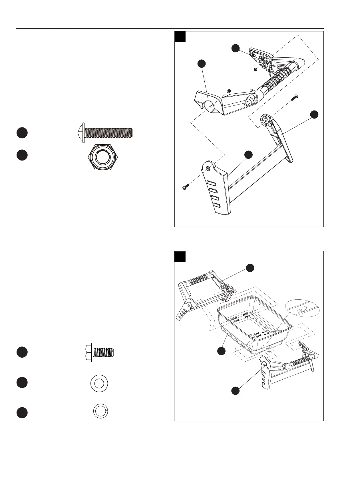
Step 7: Attach Left Assembly and Right
Assembly
Attach the left & right assembly onto the bottom
bowl (M) with eight M5 x 12 bolts (BB), eight Ø5
washers (JJ) and eight Ø5 lock washers (MM).
NOTE:
Just fully tighten all screws before both
handles are attached.
Hardware Used
6
7
V
U
M
Y
Y
X
S
M6
Nut
x 2
M6 x 25
Screw
x 2
FF
HH
M5 x 12
Bolt
x 8
BB
Ø5
Washer
x 8
JJ
Ø5
Lock
Washer
x 8
MM