LGE Internal Use OnlyCopyright © 2007 LG Electronics. Inc. All right reserved.
Only for training and service purposes
- 12 -
* Before White-balance, the AV ADC should be done.
7. White Balance
* Test Equipment
Color Analyzer (CA-210/CH.9)
-> When you adjust LCD color temperature, on Color
analyzer (CA-210), you should use Channel 9 which is
Matrix compensated (White, Red, Green, Blue revised) by
CS-1000 and adjust in accordance with White balance
adjustment coordinate which is specified on the next.
* Color temperature standards according to CSM and Module
Cool : 11,000k
Medium : 9,300k
Warm : 6,500k
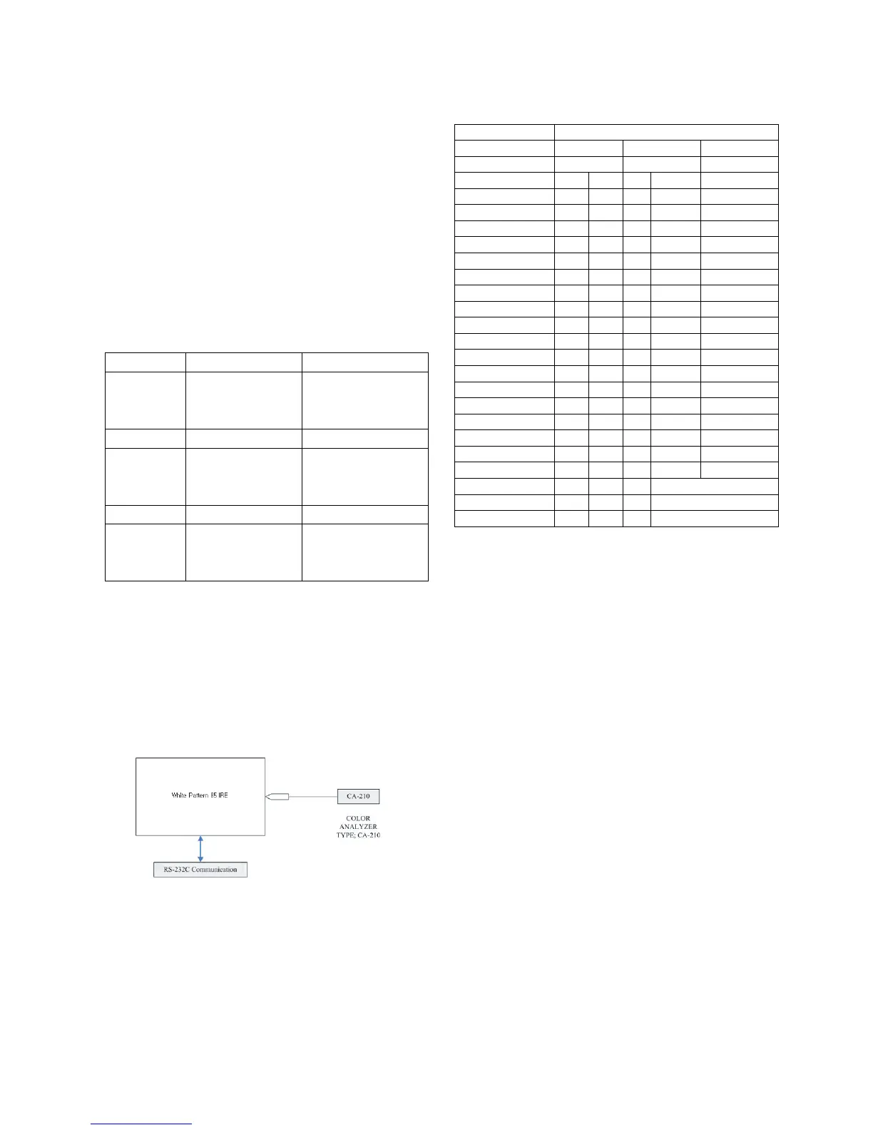
* White balance adjustment coordinate and color temperature
- PC (for communication through RS-232C)
-> UART Baud rate : 115200 bps
- Luminance Y AV : upper 100 cd/m
2
(Typ : 250 cd/m
2
)
-> Applying to Cool, Medium, Warm mode
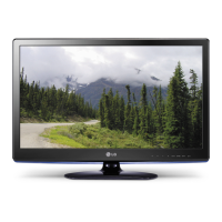
* Connecting picture of the measuring instrument (On
Automatic control )
Inside PATTERN is used when W/B is controlled. Connect to
auto controller or push control R/C IN-START
-> Enter the mode of White-Balance, the pattern will come
out.
* Auto adjustment Map (RS-232C)
* Auto-control interface and directions
1) Adjust in the place where the influx of light like floodlight
around is blocked. (illumination is less than 10ux).
2) Adhere closely the Color Analyzer ( CA-210 ) to the
module less than 10cm distance, keep it with the surface
of the Module and Color Analyzer’s Prove
vertically.(80~100°).
3) Aging time
- After aging start, keep the power on (no suspension of
power supply) and heat-run over 15 minutes.
- Using ‘no signal’ or ‘full white pattern’ or the others,
check the back light on.
7.1. Auto white Balance
(Set:RS-232, Host:PC, Baud Rate:115200bps, Download:Cortez)
Inside pattern is used when balance is controlled.
Connect as below figure and click the start button on W/B
execution program.
W/B is automatically processing Cool --> Medium --> Warm in
order.
When W/B is completed, you can see ‘OK’ on PC monitor.
Type LD73B
Baud Rate Data bit Stop bit Parity
115200 8 1 None
Index Cmd 1 Cmd 2 Data Min Value Max Value
R-Gain_Normal j a 00(00) 128(80)
G-Gain_Normal j b 00(00) 128(80)
B-Gain_Normal j c 00(00) 128(80)
R-Gain_Warm j d 00(00) 128(80)
G-Gain_Warm j e 00(00) 128(80)
B-Gain_Warm j f 00(00) 128(80)
R-Gain_Cool j g 00(00) 128(80)
G-Gain_Cool j h 00(00) 128(80)
B-Gain_Cool j i 00(00) 128(80)
R-Offset_Normal l j 00(00) 128(80)
G-Offset_Normal l k 00(00) 128(80)
B-Offset_Normal l l 00(00) 128(80)
R-Offset_Warm l m 00(00) 128(80)
G-Offset_Warm l n 00(00) 128(80)
B-Offset_Warm l o 00(00) 128(80)
R-Offset_Cool l p 00(00) 128(80)
G-Offset_Cool l q 00(00) 128(80)
B-Offset_Cool l r 00(00) 128(80)
Internal Pattern signal w b 00 Starting W/B ADJ
Internal Pattern signal w b 10 Using internal Pattern
Internal Pattern signal w b ff Ending W/B ADJ
Cool CS-1000 CA-210(CH 9)
x 0.276 0.276±0.002
y 0.283 0.283±0.002
Δuv 0.000 0.000
Medium CS-1000 CA-210(CH 9)
x 0.285 0.285±0.002
y 0.293 0.293±0.002
Δuv 0.000 0.000
Warm CS-1000 CA-210(CH 9)
x 0.313 0.313±0.002
y 0.329 0.329±0.002
Δuv 0.004 0.004
<Fig. 2> Connecting picture (On Automatic Control)