EasyManuals Logo

LG AMNH12GD4L0 Manuals

LG AMNH12GD4L0
254 pages
To Next Page IconTo Next Page
To Previous Page IconTo Previous Page
Page #84 background imageLoading...
Page #84 background image
- 84 -
Copyright ©2007 LG Electronics. Inc. All right reserved.
Only for training and service purposes
LGE Internal Use Only
Installation
Facing upwards
Viewed from point A
in direction of arrow
Horizontal
plane
Gas Pipe
Ø19.05
Ø19.05
Liquid Pipe
Within +/- 10°
A
Ø9.52
Ø9.52
Ø9.52
Ø19.05
Y branch
A
B
To Outdoor Unit
[unit:mm]
To BD Unit
A
B
Liquid and gas
pipe joints
Insulator
(included with kit)
Insulator for
field piping
Tape
(field supply)
Liquid and gas
pipe joints
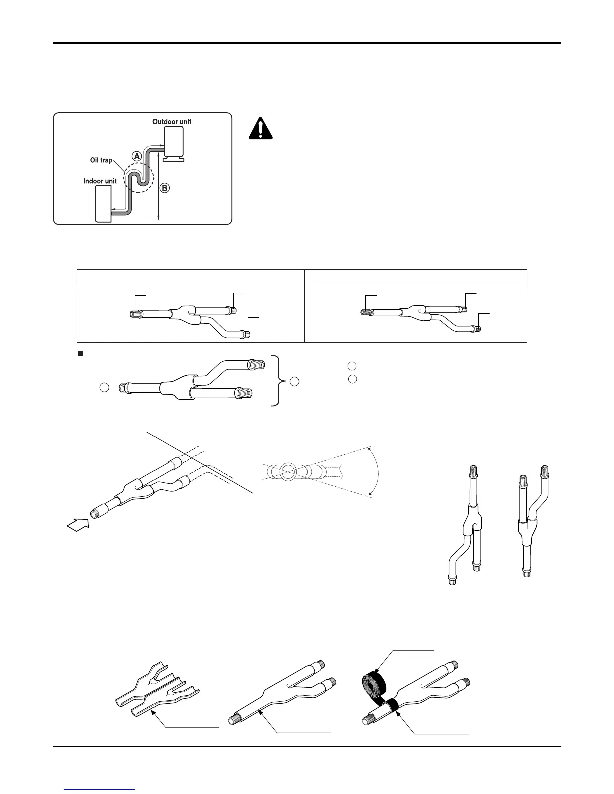
2.6 Y-Branch(Standard accessory)
• Ensure that the branch pipes are attached horizontally or vertically (see the diagram below.)
• There is no limitation on the joint mounting configuration.
If the diameter of the refrigerant piping selected by the procedures described is different from the size
of the joint, the connecting section should be cut with a pipe cutter.
• Branch pipe should be insulated with the insulator in each kit.
2.5 Necessity of a trap
Since there is fear of the oil held inside the riser piping flowing back into the compressor when stopped and caus-
ing liquid compression phenomenon, or cases of deterioration of oil return, it will be necessary to provide a trap at
an appropriate place in the riser gas piping.
In case more then 5m
CAUTIONS
Capacity is based on standard length and maximum
allowance length is on the basis of reliability.
Oil trap should be installed every 5~7 meters.

Table of Contents

Other manuals for LG AMNH12GD4L0

Questions and Answers:

Question and Answer IconNeed help?

Do you have a question about the LG AMNH12GD4L0 and is the answer not in the manual?

LG AMNH12GD4L0 Specifications

General IconGeneral
BrandLG
ModelAMNH12GD4L0
CategoryAir Conditioner
LanguageEnglish

Related product manuals