- 92 -
Copyright ©2007 LG Electronics. Inc. All right reserved.
Only for training and service purposes
LGE Internal Use Only
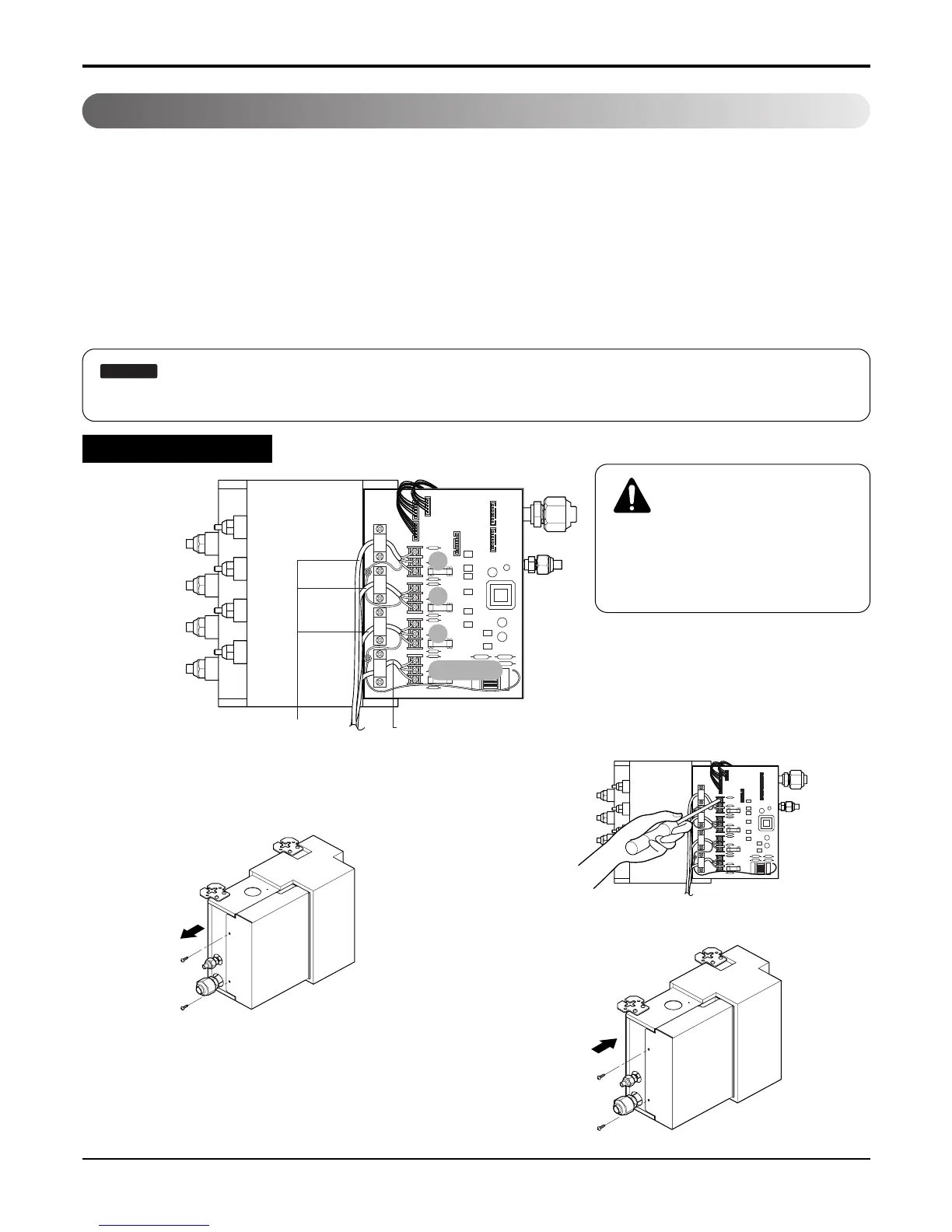
(1) Remove the control cover. Loosen the two screws,
and slide thecover in thedirection of thearrow.
(2) Perform wiring with reference the wiring diagram on
a control cover of outdoor unit. Allow 300 mm for the
pulling-out section of harness. Fix the wires com-
pletely with wire clamps(4 locations).
(3) Put in the cover in the direction of the arrow then
tighten the screws.
Installation
• Connect refrigerant pipes and connection wires to the appropriate ports maked with matching alphabets (A, B and
C) on this unit.
• Follow the instructions on the wiring nameplate to connect the connection wires of indoor/outdoor units to terminal
board numbers.(1, 2 and 3) Always fix each ground wire separately with a ground screw.(See the figure below.)
• After completing the wiring, fix the outer coating of wires securely with wire clamps. The wire clamp on indoor unit
side is furnished. Follow the procedure below to install.
• Refer to the circuit diagram on the control cover inside outdoor unit.
:
The terminal board numbers are arranged from top to bottom in order of 1, 2 and 3.
Warning
Do not use tapped wires, stand wires,
extensioncords, or starbust connec-
tions, as they may cause overtheating,
electrical shock, or fire.
 Loading...