ENGLISH
Installation Manual 65
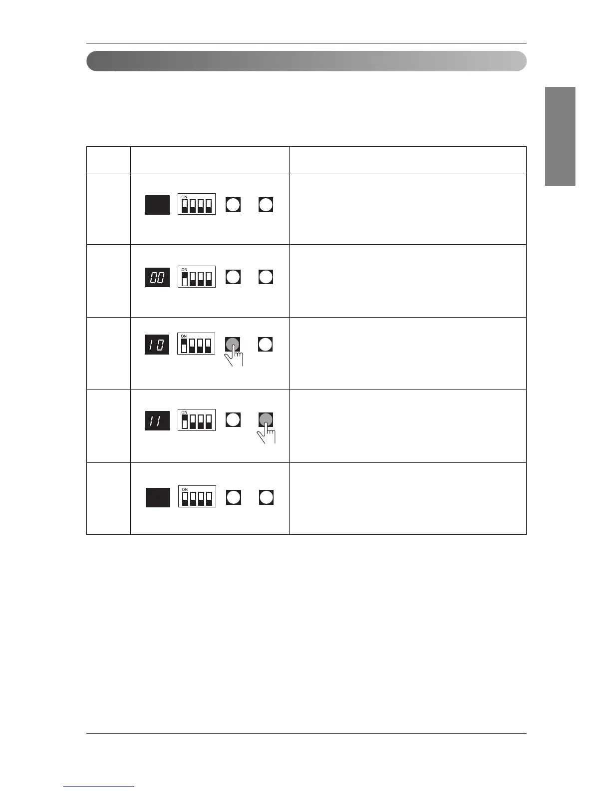
Example of manual valve addressing
(In case that an indoor unit of central control address "11" is connected to a valve #1 of an
HR unit)
• Prerequisite for manual valve addressing: central control address of each indoor unit must be preset differ-
ently at its wired remote control
- Above setup must be done for all HR unit valves.
- The valve that is not connected with any indoor unit should be addressed with any other number than used
address numbers of the valves connected with indoor units.
(The valves does not work if the address numbers are same.)
• Operation: None
• Display: None
No.
1
2
3
4
5
Display and setup Setup and Contents
• Operation: Turn dip S/W No.1 on to address valve #1
• Display: Existing value saved in EEPROM is displayed in
7-SEG.
• Operation: Set the digit of 10 to the number in Group High data
of the wired remote control connected to the corresponding
indoor unit to the valve #1 by pressing left tack S/W.
• Display: Digit increasing with the times of pressing tack S/W is
displayed in left 7-SEG
• Operation: Set the digit of 1 to the number in Group Low data
of the wired remote control connected to the corresponding
indoor unit to the valve #1 by pressing right tack S/W.
• Display: Digit increasing with the times of pressing tack S/W is
displayed in right 7-SEG
• Operation: Turn dip S/W No.1 off to save the address of
valve #1
• Display: "11" displayed in 7-SEG disappears