Electrical Wiring
Dip switch setting
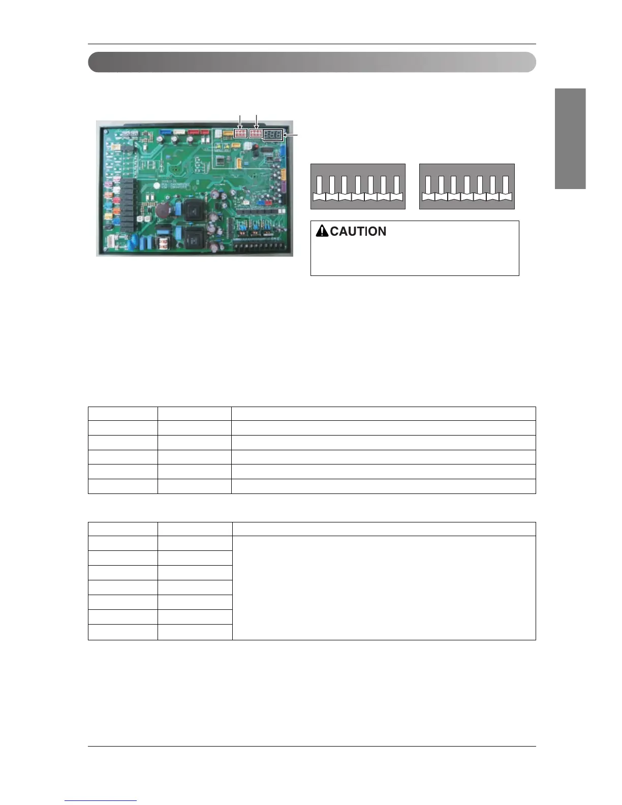
1. Location of setting switch
2. Dip switch setting
1) Set the dip switch and turn on the power of the outside unit to check whether the set value is correctly
entered in the 7 segment.
2) This function is shown for only 2 seconds after the power is connected.
■ Check outside unit setting
• The number on the 7 segment is displayed in order after the power is connected.
• This number represents the setting condition.
■ Mode code
If the applicable dip switch is not set correctly,
the product may not operate properly.
Order Number Item
1 - Model code
2 - Total capacity(HP)
3 2 Heat pump model
4 25 Normal mode display (If the dip switch is set incorrectly, it is not displayed.)
5 41 Refrigerant type (R410A)
Model Code Capacity(HP) Refrigerant
143 8
144 10
145 20
145, 144 30 R410A
145, 145 40
145, 145, 144 50
145, 145, 145 60
ENGLISH
Installation Manual 67