Do you have a question about the LG ATNH306FLFC and is the answer not in the manual?
Explains the structure and meaning of the Indoor Unit model number.
Explains the structure and meaning of the Outdoor Unit model number.
Provides general safety warnings and symbol meanings.
Details safety measures for installing the air conditioner.
Safety advice for re-installation, storage, and handling.
Safety instructions for operating the air conditioner.
Safety considerations for installation location and environment.
Safety regarding power cables, children, noise, and corrosive environments.
Safety for operation, connections, installation area, and product transportation.
Safety for packing material disposal, power switch, and general maintenance.
Lists model names for various indoor unit types and capacities.
Lists model names for outdoor units based on capacity and type.
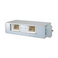
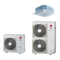
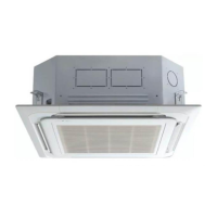
Visuals of Indoor Units: Ceiling Cassette, Ceiling & Floor, Duct types.
Visuals of Outdoor Units: AUUH488C, AUUH728C, AUUH1008C.
Provides dimensions for the Indoor Unit, focusing on Cassette TE type.
Detailed dimensions for the Cassette TF type indoor unit.
Detailed dimensions for the Cassette TD type indoor unit.
Dimensions for Ceiling & Floor Convertible indoor units (VB, VE).
Dimensions for Ceiling Concealed Duct indoor units (BH, BG, BR).
Dimensions for the AUUH488C outdoor unit.
Dimensions for the AUUH728C outdoor unit.
Dimensions for the AUUH1008C outdoor unit.
Detailed specifications for Ceiling Cassette - 4 Way indoor units.
Detailed specifications for Ceiling Concealed Duct - High Static indoor units.
Detailed specifications for Ceiling & Floor Convertible indoor units.
Technical specifications for the AUUH488C outdoor unit.
Technical specifications for the AUUH728C outdoor unit.
Technical specifications for the AUUH1008C outdoor unit.
Lists necessary parts and tools for cassette type indoor unit installation.
Guidelines for choosing the optimal installation location for the indoor unit.
Details ceiling opening sizes and hanging bolt positions for different models.
Specific locations to avoid for installation and related precautions.
Instructions for connecting indoor unit power and remote control wires.
Steps for installing the indoor unit's decoration panel correctly.
Guidelines for proper drain piping installation and drain pump testing.
Lists standard and optional accessories included or available for the unit.
Lists required parts and tools for installing convertible type units.
Details wiring connections for convertible indoor units.
Important declination and insulation requirements for convertible unit installation.
Electrical wiring precautions, circuit breaker, and power supply considerations.
Lists standard and optional accessories for installation.
Guidelines for selecting the optimal installation location for concealed duct units.
Details ceiling dimensions and hanging bolt positions for concealed duct units.
Instructions for connecting cables and clamping them securely.
Requirements for thermal insulation of indoor unit piping.
Procedure to check the indoor unit's drainage system for proper function.
Ensuring correct drain piping slope and U-trap installation to prevent issues.
Lists standard and optional accessories for installation.
Steps for preparing pipes: cutting, burr removal, and nut fitting.
Procedure for flaring copper tubes and checking the quality of the flare.
Instructions for disassembling the remote controller and its wiring.
Guidelines for choosing the optimal installation location for AUUH728C outdoor unit.
Specifies minimum clearance and service space for AUUH728C outdoor unit.
Clearance requirements for AUUH728C when surrounded by walls or obstructed above.
Space requirements for installing multiple AUUH728C units together.
Specifies minimum clearance and service space for AUUH1008C outdoor unit.
Clearance requirements for AUUH1008C in various installation configurations.
Details on how to anchor the AUUH728C outdoor unit securely.
Details on how to anchor the AUUH1008C outdoor unit securely.
Instructions and precautions for safely lifting the outdoor unit.
Specifies maximum piping lengths and height differences for optimal performance.
Steps for connecting refrigerant pipes, including welding and tightening.
Method for calculating and adding refrigerant for AUUH488C.
Method for calculating and adding refrigerant for AUUH728C/AUUH1008C.
Details branch pipe types and specifications for connection parts.
Instructions for securely wrapping branch pipes with thermal insulation materials.
Highlights compliance with local regulations and proper grounding.
Steps for performing auto addressing for simultaneous indoor unit operation.
Procedure for operating multiple indoor units simultaneously.
Important precautions and steps for performing the test run.
Items to check after installation is complete for proper operation.
Explanation of the operation indicators (Operation, Sleep Timer, Timer, Defrost).
How the unit operates in Cooling Mode based on temperature.
Operation logic for Soft Dry Mode, including fan speed and temperature settings.
How the unit operates in Heating Mode based on temperature.
Explanation of the defrost control logic during heating operation.
Details on how Fuzzy Logic selects operation modes based on intake air temperature.
Fuzzy logic operation for Dehumidification and Heating modes.
Controls for fan speed selection, On-Timer, and Off-Timer operations.
Details on timer functions, Chaos modes, Jet Cool, and Auto Restart.
Forced operation mode and explanation of buzzer sound indications.
Diagram and description of the CST type remote controller's functions.
Diagram and description of the Duct type remote controller's functions.
Diagram and description of the Convertible type remote controller's functions.
Detailed explanation of each button on the convertible type remote controller.
Detailed explanation of each button on the CST type remote controller.
Detailed explanation of each button on the duct type remote controller.
Configuration for the two-thermistor system in wired remote controllers.
Procedure to adjust indoor fan speed based on ceiling height for cassette units.
How to set External Static Pressure for duct type units.
Step-by-step guide to set E.S.P. using the remote controller.
Highlights the features and capabilities of the Simple Central Control system.
Explanation of the parts and functions of the Simple Central Control unit.
Diagram showing the overall connection of central control systems.
Detailed wiring diagram for a simple central control setup.
Wiring for connecting two or more central controls.
Procedure for setting up the PI485 module for network communication.
Steps to set the indoor unit address using a wired remote.
Steps to set the indoor unit address using a wireless remote.
Procedure for conducting the test run after installation.
Cautions regarding installation location and handling the unit.
Steps for installing the controller unit.
Instructions for linking connecting wires between the controller and unit.
Configuration of rotary and DIP switches for central control.
Lists optional accessories for central control systems.
Overview of the Deluxe Central Control system's capabilities and benefits.
Monitoring and controlling individual or groups of air conditioners.
Organizing air conditioners into groups for easier management.
System self-diagnosis function and convenient maintenance aspects.
User interface, scheduling, power backup, and mobility features.
System scalability, installation ease, and upgrade capabilities.
Functions for system control, monitoring, and status checks.
Configuration for system setup, grouping, and scheduling.
Details on the centralized control system, touch pad, GUI, and power backup.
Specifications for the CNU and PI485 interface units.
Circuit diagram for the Cassette Type indoor unit's electronic control.
Circuit diagram for the Duct Type indoor unit's electronic control.
Circuit diagram for the Convertible Type indoor unit's electronic control.
Wiring diagrams for AUUH488C, AUUH728C, and AUUH1008C outdoor units.
Wiring diagram for Cassette Type indoor units.
Wiring diagrams for Duct Type indoor units (BH, BG, BR).
Wiring diagrams for AUUH488C, AUUH728C, and AUUH1008C outdoor units.
Component layout for Cassette Type indoor units (TE/TF/TD chassis).
Component layout for Duct Type indoor units (BH chassis).
Component layout for Duct Type indoor units (BG/BR chassis).
Component layout for Convertible Type indoor units (VB chassis).
Component layout for Convertible Type indoor units (VE chassis).
Component layout for AUUH Series outdoor units (Component Side).
Component layout for AUUH Series outdoor units (Solder Side).
Refrigerant piping diagram for AUUH488C Synchro Duo system.
Refrigerant piping diagram for AUUH488C Synchro Trio system.
Refrigerant piping diagram for AUUH488C Synchro Quartet system.
Refrigerant piping diagram for AUUH728C Synchro Duo system.
Refrigerant piping diagram for AUUH728C Synchro Trio system.
Refrigerant piping diagram for AUUH728C Synchro Quartet system.
Refrigerant piping diagram for AUUH1008C Synchro Duo system.
Refrigerant piping diagram for AUUH1008C Synchro Trio system.
Refrigerant piping diagram for AUUH1008C Synchro Quartet system.
Troubleshooting based on temperature difference and operating current.
Checking refrigeration cycle parameters like suction pressure and temperature.
Steps to diagnose why the product is not operating at all.
Diagnosing issues when the product does not respond to the remote controller.
Steps to diagnose why the cooling function is not working.
Steps to diagnose why the heating function is not working.
Diagnosing why the indoor fan is not operating.
Diagnosing issues with the vertical louver movement.
Table of error codes and their descriptions for indoor units.
Table of error codes and their descriptions for outdoor units.
Checking and diagnosing errors related to indoor air sensors.
Diagnosing errors for indoor inlet and outlet pipe sensors.
Troubleshooting steps for communication errors between components.
Steps to diagnose errors related to the drain pump and float switch.
Troubleshooting communication issues between indoor and outdoor units.
Troubleshooting steps for DC Peak errors, checking compressor and IPM.
Troubleshooting steps for current detection and C/T errors.
Troubleshooting for Press S/W and input voltage errors.
Troubleshooting compressor position detect and PSC fault errors.
Troubleshooting high temperature errors for D-pipes in inverter and constant units.
Troubleshooting for errors related to multiple sensors (D-pipe, Air, Condenser, etc.).
Troubleshooting capacity errors and EEPROM check sum errors.
Troubleshooting steps for phase errors, checking main power and connectors.
Troubleshooting high temperature errors for condenser pipe and heat sink sensors.
Details valve positions for shipping, purging, operation, pumping down, and servicing.
Step-by-step guide for pumping down the refrigerant system.
Steps for evacuating the refrigerant system using a vacuum pump.
Steps for charging the system with refrigerant after evacuation.
Explanation of Auto Swing, Soft-Dry, Cooling, and Swirl Swing controls.
Operation logic for heating mode and hot-start control.
Explanation of Soft-Dry and Cooling Mode operations for duct units.
Operation logic for heating mode for duct units.
Operation logic for hot-start control in duct type units.
Explanation of Soft-Dry and Cooling Mode operations for ceiling & floor units.
Operation logic for heating mode for ceiling & floor units.
Operation logic for hot-start control in ceiling & floor units.
Basic control functions for Compressor, Fan, EEV, and 4-way valve.
How compressor operation steps are determined by temperature differences.
Graphs showing compressor operation fields for Cooling and Heating modes.
How EEV open degree is set and controlled after compressor starts.
EEV control logic for normal operation in cooling and heating modes.
Control logic to prevent compressor damage based on discharge temperature.
Fan operation modes: Stop/Operation and Phase Control.
How the reversing valve operates during cooling, heating, and defrosting.
Conditions required for the defrost process to initiate.
Details on defrost cycle duration and process steps.
Logic for equalizing oil level among compressors.
Function to prevent compressor damage based on discharge pipe temperature.
Control based on outdoor pipe temperature and abnormal sensor detection.
System behavior related to high/low pressure switch operations.
Exploded view and part numbers for Ceiling Cassette TE chassis.
Exploded view and part numbers for Ceiling Cassette TF chassis.
Exploded view diagram for Ceiling Cassette TF chassis.
Exploded view diagram for Ceiling Cassette TD chassis.
Exploded view diagram for Duct Type BH/BG chassis.
Exploded view diagram for Duct Type BR chassis.
Exploded view diagram for Convertible Type VE chassis.
Exploded view diagram for Convertible Type VB chassis.
Exploded view diagram for AUUH488C outdoor unit.
Exploded view diagram for AUUH728C outdoor unit.
Exploded view diagram for AUUH1008C outdoor unit.
Exploded view diagram for the PT-HEC1 chassis.
Exploded view diagram for the PT-HFC chassis.
Exploded view diagram for the PT-HDC1 chassis.
| Brand | LG |
|---|---|
| Model | ATNH306FLFC |
| Category | Air Conditioner |
| Language | English |