Do you have a question about the LG CM9530 and is the answer not in the manual?
Safety guidelines for handling sensitive components like the pick-up.
Measures to prevent damage from static electricity to sensitive devices.
Special function activation using front keys and remote.
Procedures for accessing and modifying EEPROM data.
Steps for updating the system firmware via USB.
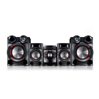
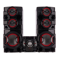
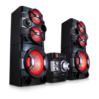
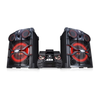
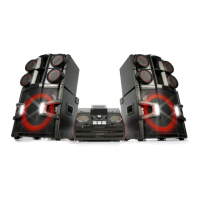
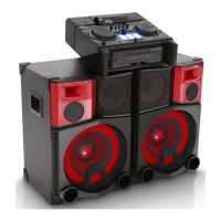
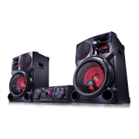
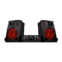
Technical details and performance characteristics of the system.
Exploded view of the main unit's chassis and frame components.
Exploded view of the optical disc mechanism.
List and illustration of included accessories and packaging materials.
Exploded views and details of the front and subwoofer speakers.
Step-by-step troubleshooting for common power and sound issues.
Flowcharts for diagnosing power supply and system operation failures.
Oscilloscope waveform examples for key signals during testing.
Diagram illustrating the interconnections between major PCB units.
High-level overview of the system's functional blocks and power distribution.
Detailed schematics for various system sections like SMPS and amplifier.
Table listing specified and measured voltages for SMPS board components.
Top and bottom views of major PCBs for component identification.
| Brand | LG |
|---|---|
| Model | CM9530 |
| Category | Stereo System |
| Language | English |