- 9 -
(a)
(a)
(a)
(a)
CN2
CN6
CN3
CN5 CN4
(a)
(a)
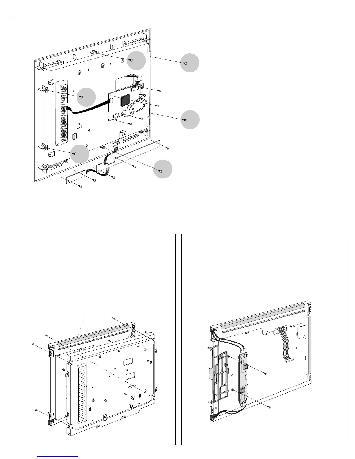
5. LCD MODULE REMOVAL
(1) Remove four screws (a).
(2) Separate the LCD Module from the Main Frame.
6. INVERTER PCB ASS’Y REMOVAL
(1) Disconnect CN2, CN3 and CN4, CN5.
(2) Remove two screws (a). (LB565D, LM565D)
(3) Remove the Inverter PCB Ass’y.
LCD Module
(a)
J5
J10
(a)
(b)
(b)
(c)
(c)
(c)
(c)
(c)
(a)
(a)
(b)
(b)
(b)
(b)
CN6
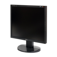
4. MAIN PCB ASS’Y & CABINET ASS’Y
REMOVAL
(1) Disconnect CN6, J5 and J10.
(2) Remove four screws (a).
(3) Remove the Main PCB Ass’y
(4) Remove six screws (b).
(5) Remove the CABINET Ass’y.
(6) Remove five screws (c).
(7) Remove the Control PCB Ass’y.
 Loading...