EasyManua.ls Logo

LG GA-B409U QA Series User Manual

LG GA-B409U QA Series
37 pages
To Next Page IconTo Next Page
To Previous Page IconTo Previous Page
Page #10 background image
ADJUSTMENT
-10-
1. COMPRESSOR
1) Role
The compressor intakes low temperature and low
pressure gas evaporated from Evaporator of the
Refrigerator, and condenses this gas to high temperature
and high pressure gas, and then plays delivering role to
Condenser.
2) Composition
The Compressor is composed of Compressor Apparatus
compressing gas, Compressor Motor moving Compressor
Apparatus and Case which protecting Compressor Apparatus
and Motor. There are PTC-Starter, and Over Load
Protector (OLP) in the Compressor outside. On the other
hand, because the Compressor consists of 1/1000mm
processing precision components and is sealed after
production in absence of dust or humidity, deal and repair
with care.
3) Note for Usage
(1) Be careful not to allow over-voltage and over current.
(2) No Strike
If applying forcible power or strike (dropping or
careless dealing), poor operation and noise may occur
(3) Use proper electric components appropriate to the
Compressor.
(4) Note to Keep Compressor.
If Compressor gets wet in the rain and rust in the pin of
Hermetic Terminal, the result may be poor operation
and poor contact may cause.
(5) Be careful that dust, humidity, and flux welding don't
inflow in the Compressor inside in replacing the
Compressor. Dust, humidity, and flux due to welding
which inflows to Cylinder may cause lockage and
noise.
2. PTC-STARTER
1) Composition of PTC-Starter
(1) PTC (Positive Temperature Coefficient) is a no-contact
semiconductor starting device which uses ceramic
material and this material consists of BaTiO3.
(2) The higher the temperature is, the higher becomes the
resistance value. These features are used as starting
device for the Motor.
2) Role of PTC-Starter
(1) PTC is attached to Hermetic Compressor used for
Refrigerator, Show Case and starts Motor.
(2) Compressor for household refrigerator applies to
single-phase induction Motor.
For normal operation of the single-phase induction motor, in
the starting operation current flows in both main coil and sub-coil.
After the starting is over, the current in subcoil is cut off. The
proper features of PTC play all the above roles. So, PTC is
used as a motor starting device.
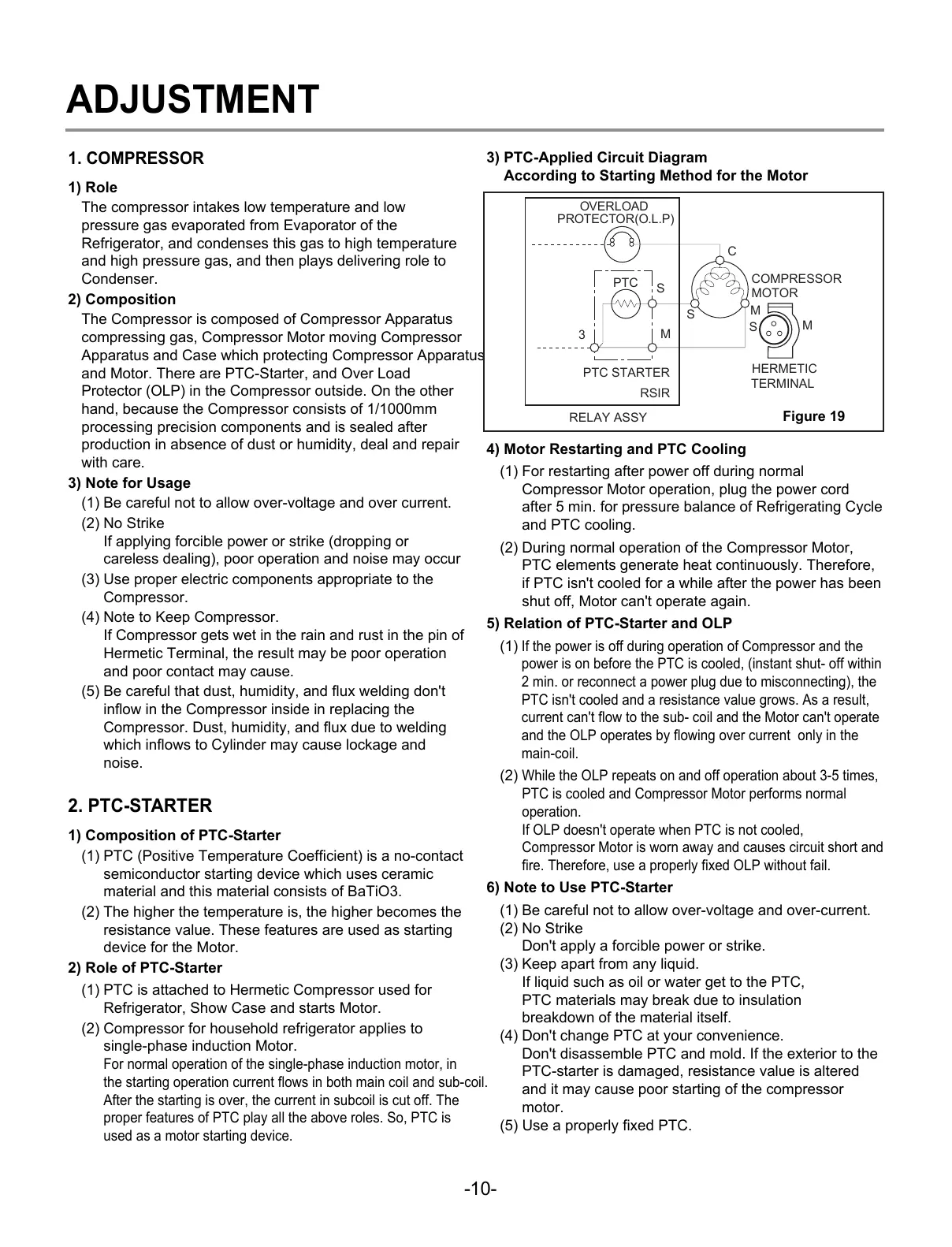
3) PTC-Applied Circuit Diagram
According to Starting Method for the Motor
4) Motor Restarting and PTC Cooling
(1) For restarting after power off during normal
Compressor Motor operation, plug the power cord
after 5 min. for pressure balance of Refrigerating Cycle
and PTC cooling.
(2) During normal operation of the Compressor Motor,
PTC elements generate heat continuously. Therefore,
if PTC isn't cooled for a while after the power has been
shut off, Motor can't operate again.
5) Relation of PTC-Starter and OLP
(1)
If the power is off during operation of Compressor and the
power is on before the PTC is cooled, (instant shut- off within
2 min. or reconnect a power plug due to misconnecting), the
PTC isn't cooled and a resistance value grows. As a result,
current can't flow to the sub- coil and the Motor can't operate
and the OLP operates by flowing over current only in the
main-coil.
(2)
While the OLP repeats on and off operation about 3-5 times,
PTC is cooled and Compressor Motor performs normal
operation.
If OLP doesn't operate when PTC is not cooled,
Compressor Motor is worn away and causes circuit short and
fire. Therefore, use a properly fixed OLP without fail.
6) Note to Use PTC-Starter
(1) Be careful not to allow over-voltage and over-current.
(2) No Strike
Don't apply a forcible power or strike.
(3) Keep apart from any liquid.
If liquid such as oil or water get to the PTC,
PTC materials may break due to insulation
breakdown of the material itself.
(4) Don't change PTC at your convenience.
Don't disassemble PTC and mold. If the exterior to the
PTC-starter is damaged, resistance value is altered
and it may cause poor starting of the compressor
motor.
(5) Use a properly fixed PTC.
PTC STARTER
HERMETIC
TERMINAL
COMPRESSOR
MOTOR
C
M
S
M
3
M
S
S
PTC
OVERLOAD
PROTECTOR(O.L.P)
RSIR
RELAY ASSY
Figure 19
All manuals and user guides at all-guides.com

Questions and Answers:

LG GA-B409U QA Series Specifications

General IconGeneral
Energy Efficiency ClassA++
Climate ClassSN-T
RefrigerantR600a
Smart DiagnosisYes
Door CoolingYes
Linear CoolingYes
Zero ClearanceYes
Multi Air FlowYes
DisplayLED

Summary

Servicing Precautions

Features of refrigerant (R600a)

Details about the characteristics of R600a refrigerant.

Installation place

Requirements for the physical location where the refrigerator is installed.

Utilities

List of necessary tools and equipment for servicing.

Make sure before Servicing

Checks and precautions to take before commencing service.

Air Recharging in Compressor

Procedure for handling refrigerant and recharging the compressor.

Specifications

Model GA-B409U*QA Specifications

Detailed specifications for the GA-B409U*QA model.

Model GA-B379U*QA Specifications

Detailed specifications for the GA-B379U*QA model.

Parts Identification

Replacement of Door Opening Type

Disassembly

DOOR

Instructions for removing the freezer and refrigerator doors.

DOOR SWITCH

Steps to access and remove the door switch.

REFRIGERATOR ROOM LAMP

Guide for removing and replacing the refrigerator lamp.

DISPLAY

Procedure for accessing and replacing the display cover.

FAN AND FAN MOTOR

Steps for disassembling the fan and fan motor assembly.

DEFROST CONTROL ASSY

Instructions for removing the defrost control assembly.

DAMPER CONTROL

Steps for disassembling the damper control unit.

HEATER, SHEATH

Procedure for removing and replacing the heater sheath.

Adjustment

COMPRESSOR

Role, composition, and usage notes for the compressor.

PTC-STARTER

Details on the PTC starter's composition, role, and application.

PTC-Applied Circuit Diagram

Circuit diagram illustrating the PTC starter's application.

Motor Restarting and PTC Cooling

Guidelines for restarting the motor and cooling the PTC.

Relation of PTC-Starter and OLP

Explanation of how the PTC starter interacts with the OLP.

Note to Use PTC-Starter

Important considerations for using the PTC starter correctly.

OLP (OVER LOAD PROTECTOR)

Definition, role, and usage notes for the Over Load Protector.

CIRCUIT DIAGRAM

Schematic diagram of the refrigerator's electrical circuits.

Troubleshooting (Mechanical Part)

COMPRESSOR AND ELECTRIC COMPONENTS

Troubleshooting steps for compressor and related electrical parts.

RELAY ASSY (PTC AND OLP)

Diagnostic procedures for the relay assembly and its components.

ANOTHER ELECTRIC COMPONENTS

Troubleshooting for other electrical components like sensors and motors.

SERVICE DIAGNOSIS CHART

A chart to diagnose common refrigerator complaints and their remedies.

Refrigerating Cycle

Troubleshooting Chart

Chart detailing causes and states for refrigerating cycle issues.

Leakage Detection

Methods for detecting refrigerant leaks in the system.

General Control of Refrigerating Cycle

Overview of components and procedures for controlling the refrigerating cycle.

MICOM FUNCTION & PCB CIRCUIT EXPLANATION

FUNCTION EXPOSITION

Overview of the refrigerator's functional modes and display board.

FUNCTION OF TEMPERATURE SELECTION

How to adjust and select temperatures for different compartments.

SUPER FREEZING

Details on the Super Freezing function and its operation.

VACATION FUNCTION

Explanation of the Vacation mode for energy saving.

BUZZER SOUND

Information on the buzzer sound produced by button presses.

DEFROSTING

Explanation of the automatic defrosting process and its timing.

ORDERLY OPERATION OF ELECTRIC PARTS

Sequence of operation for key electric components.

SELF-TEST

Functionality and procedure for the refrigerator's self-test mode.

ERROR CODE LEDs

How error codes are represented using LEDs and their meanings.

FUNCTION TEST

Procedure for testing the refrigerator's functions and diagnosing faults.

Function Description

ELECTRIC CIRCUITS

Description of the main electrical circuits, including power and supply.

OSCILLATION CIRCUIT

Explanation of the oscillation circuit used for timing and clock generation.

RESET CIRCUIT

Description of the reset circuit for initializing MICOM functions.

LOAD/BUZZER OPERATION

Checking load operations and buzzer functions.

TEMP SENSOR CIRCUITS

Explanation of temperature sensor circuits and their readings.

SWITCH INPUT CIRCUIT

Description of the switch input circuit for testing.

TEMPERATURE COMPENSATION

Table and explanation for temperature compensation adjustments.

SENSOR RESISTANCE CHARACTERISTICS TABLE

MAIN PCB ASS'Y AND PARTS LIST

Identification and list of parts on the main PCB assembly.

REPLACEMENT PARTS LIST

PCB ASS'Y, DISPLAY AND PARTS LIST

PCB assembly,MAIN circuit drawing

PCB assembly,display circuit drawing

EXPLODED VIEW & REPLACEMENT PARTS LIST

Related product manuals