EasyManua.ls Logo

LG GA-B409U QA Series User Manual

LG GA-B409U QA Series
37 pages
To Next Page IconTo Next Page
To Previous Page IconTo Previous Page
Page #9 background image
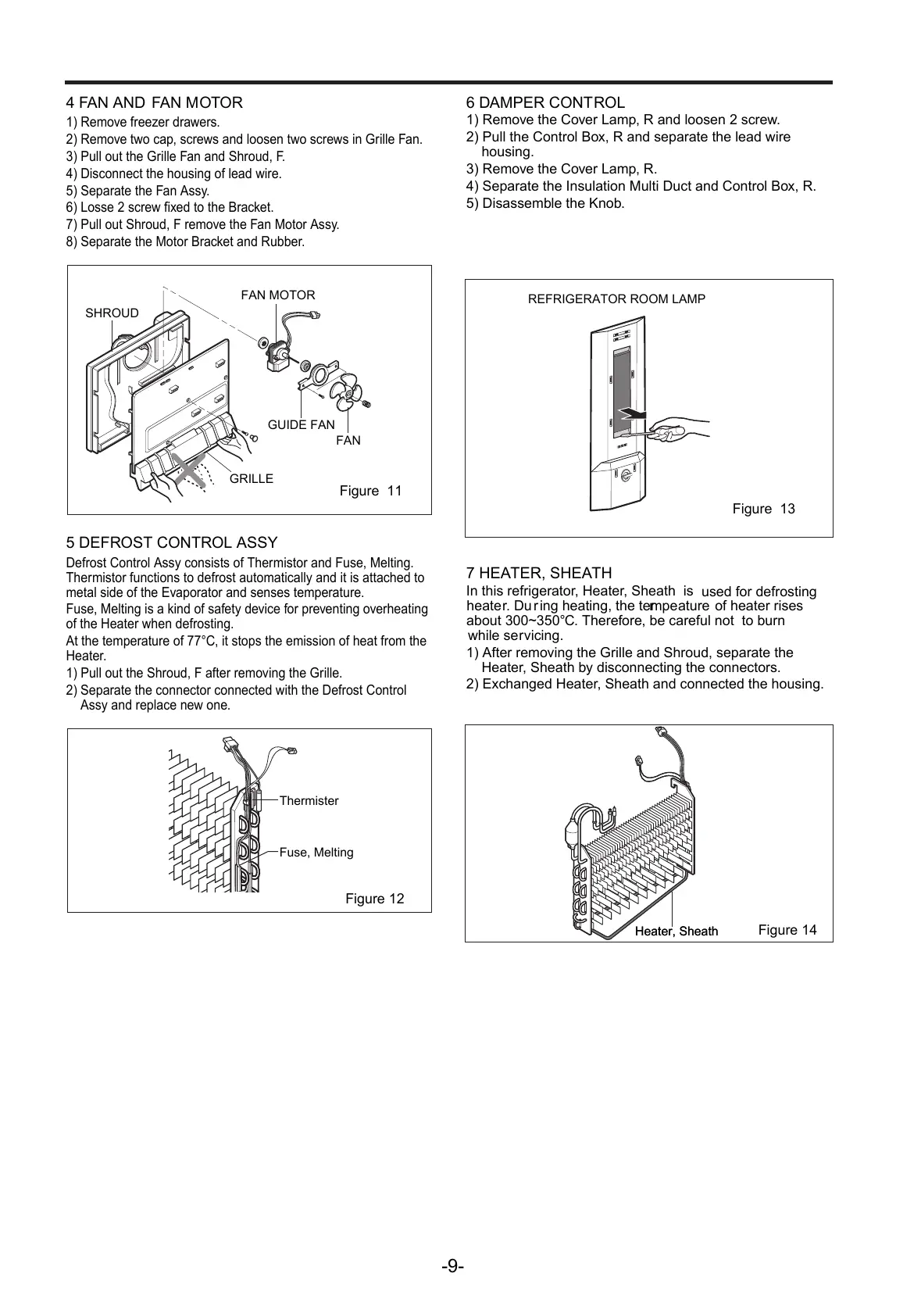
4 F AN AND F AN M O T OR
1) Rem o v e free z er d r a w er s .
2) Rem o v e t w o ca p , scr e ws and loosen t w o scr e ws in G r ille F an.
3) Pull out the G r ille F an and Shroud, F .
4) Disconnect the housing of lead wir
e .
5) Sepa r ate the F an Ass y .
6) Losse 2 scr e w fi x ed to the B r ack et.
7) Pull out Shroud, F rem o v e the F an Motor Ass y .
8) Sepa r ate the Motor B r ack et and Ru b be r .
5 DEF R OST CONT R OL ASSY
Defrost Control Assy consists of The r mistor and Fus e , Melting.
The r mistor functions to defrost automatically and it is attached to
metal side of the E
v apo r ator and senses tempe r atur e .
Fus e , Melting is a kind of sa f ety d e vice f or pr e v enting o v erheating
of the Heater when defrosting.
At the tempe r ature of 7 7 ° C , it stops the emission of heat from the
Heate
r .
1) Pull out the Shroud, F after rem o ving the G r ill e .
2) Sepa r ate the connector connected with the Defrost Control
Assy and replace n e w on e .
6 D AMPER CONT R OL
1) Rem o v e the C o v er Lam p , R and loosen 2 scr e w .
2) Pull the Control B o x, R and sepa r ate the lead wire
housing.
3) Rem o v e the C o v er Lam p , R.
4) Sepa r ate the Insulation Multi Duct and Control B o x, R.
5) Disassem b le the Kno b .
7 HE A TER, SHE A TH
In this ref r ige r ato r , Heate r , Sheath is
used for defrosting
heate r . Du r ing heating, the tempe r ature
of heater rises
about 300~350° C . There f or e , be careful not
to burn
while se r vicing.
1) After rem o ving the G r ille and Shroud, sepa r ate the
Heate r , Sheath b y disconnecting the connector s .
2) Exchanged Heate r , Sheath and connected the housing.
REFRIGERATOR ROOM LAMP
GUIDE FAN
FAN
SHROUD
FAN MOTOR
GRILLE
Figure 13
Figure 11
-9-
Figure 12
Figure 14
Thermister
Fuse, Melting
Heater, Sheath Heater, Sheath
All manuals and user guides at all-guides.com

Questions and Answers:

LG GA-B409U QA Series Specifications

General IconGeneral
Energy Efficiency ClassA++
Climate ClassSN-T
RefrigerantR600a
Smart DiagnosisYes
Door CoolingYes
Linear CoolingYes
Zero ClearanceYes
Multi Air FlowYes
DisplayLED

Summary

Servicing Precautions

Features of refrigerant (R600a)

Details about the characteristics of R600a refrigerant.

Installation place

Requirements for the physical location where the refrigerator is installed.

Utilities

List of necessary tools and equipment for servicing.

Make sure before Servicing

Checks and precautions to take before commencing service.

Air Recharging in Compressor

Procedure for handling refrigerant and recharging the compressor.

Specifications

Model GA-B409U*QA Specifications

Detailed specifications for the GA-B409U*QA model.

Model GA-B379U*QA Specifications

Detailed specifications for the GA-B379U*QA model.

Parts Identification

Replacement of Door Opening Type

Disassembly

DOOR

Instructions for removing the freezer and refrigerator doors.

DOOR SWITCH

Steps to access and remove the door switch.

REFRIGERATOR ROOM LAMP

Guide for removing and replacing the refrigerator lamp.

DISPLAY

Procedure for accessing and replacing the display cover.

FAN AND FAN MOTOR

Steps for disassembling the fan and fan motor assembly.

DEFROST CONTROL ASSY

Instructions for removing the defrost control assembly.

DAMPER CONTROL

Steps for disassembling the damper control unit.

HEATER, SHEATH

Procedure for removing and replacing the heater sheath.

Adjustment

COMPRESSOR

Role, composition, and usage notes for the compressor.

PTC-STARTER

Details on the PTC starter's composition, role, and application.

PTC-Applied Circuit Diagram

Circuit diagram illustrating the PTC starter's application.

Motor Restarting and PTC Cooling

Guidelines for restarting the motor and cooling the PTC.

Relation of PTC-Starter and OLP

Explanation of how the PTC starter interacts with the OLP.

Note to Use PTC-Starter

Important considerations for using the PTC starter correctly.

OLP (OVER LOAD PROTECTOR)

Definition, role, and usage notes for the Over Load Protector.

CIRCUIT DIAGRAM

Schematic diagram of the refrigerator's electrical circuits.

Troubleshooting (Mechanical Part)

COMPRESSOR AND ELECTRIC COMPONENTS

Troubleshooting steps for compressor and related electrical parts.

RELAY ASSY (PTC AND OLP)

Diagnostic procedures for the relay assembly and its components.

ANOTHER ELECTRIC COMPONENTS

Troubleshooting for other electrical components like sensors and motors.

SERVICE DIAGNOSIS CHART

A chart to diagnose common refrigerator complaints and their remedies.

Refrigerating Cycle

Troubleshooting Chart

Chart detailing causes and states for refrigerating cycle issues.

Leakage Detection

Methods for detecting refrigerant leaks in the system.

General Control of Refrigerating Cycle

Overview of components and procedures for controlling the refrigerating cycle.

MICOM FUNCTION & PCB CIRCUIT EXPLANATION

FUNCTION EXPOSITION

Overview of the refrigerator's functional modes and display board.

FUNCTION OF TEMPERATURE SELECTION

How to adjust and select temperatures for different compartments.

SUPER FREEZING

Details on the Super Freezing function and its operation.

VACATION FUNCTION

Explanation of the Vacation mode for energy saving.

BUZZER SOUND

Information on the buzzer sound produced by button presses.

DEFROSTING

Explanation of the automatic defrosting process and its timing.

ORDERLY OPERATION OF ELECTRIC PARTS

Sequence of operation for key electric components.

SELF-TEST

Functionality and procedure for the refrigerator's self-test mode.

ERROR CODE LEDs

How error codes are represented using LEDs and their meanings.

FUNCTION TEST

Procedure for testing the refrigerator's functions and diagnosing faults.

Function Description

ELECTRIC CIRCUITS

Description of the main electrical circuits, including power and supply.

OSCILLATION CIRCUIT

Explanation of the oscillation circuit used for timing and clock generation.

RESET CIRCUIT

Description of the reset circuit for initializing MICOM functions.

LOAD/BUZZER OPERATION

Checking load operations and buzzer functions.

TEMP SENSOR CIRCUITS

Explanation of temperature sensor circuits and their readings.

SWITCH INPUT CIRCUIT

Description of the switch input circuit for testing.

TEMPERATURE COMPENSATION

Table and explanation for temperature compensation adjustments.

SENSOR RESISTANCE CHARACTERISTICS TABLE

MAIN PCB ASS'Y AND PARTS LIST

Identification and list of parts on the main PCB assembly.

REPLACEMENT PARTS LIST

PCB ASS'Y, DISPLAY AND PARTS LIST

PCB assembly,MAIN circuit drawing

PCB assembly,display circuit drawing

EXPLODED VIEW & REPLACEMENT PARTS LIST

Related product manuals