Do you have a question about the LG GCWF1069CS1 and is the answer not in the manual?
Provides essential warnings regarding fire, electric shock, and injury prevention during operation.
Details proper grounding procedures for safe appliance operation and to prevent electric shock.
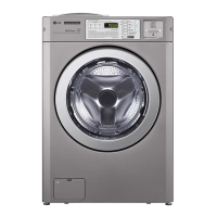
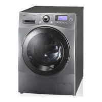
Highlights features like Direct Drive, large door opening, ultra capacity, stainless steel drum, and tub clean.
Explains water level sensing, door locking mechanisms, and conditions when the door cannot be opened.
Details the conditions under which the door locked lamp lights up and how it can be canceled.
Step-by-step guide on how to remove shipping bolts and braces before operating the appliance.
Specifies required space around the washer and provides key machine dimensions for proper installation.
Outlines minimum clearances needed for installing the washer in a recessed area, ensuring ventilation and access.
Instructions for installing the auto dosing system, including detergent and input period settings.
Details the wiring connections for the auto dosing system interface, specifying wire colors and signals.
Guidance on placing the washer on a firm surface to minimize noise and vibration.
Instructions for correctly connecting the power plug to prevent electrical hazards.
Instructions on how to properly level the washing machine using adjustable feet to minimize noise and vibration.
Covers important electrical connection points, fuse requirements, and precautions for the power cord.
Procedure for connecting hot and cold water supply hoses, including pressure requirements and leak prevention.
Instructions for correctly installing the drain hose to prevent flooding, damage, and ensure proper drainage.
Introduces the control panel layout and features for different machine types (Coin, Card/OPL).
Explains the function of the Display LED and Status LEDs for cycle indication and error messages.
Details the usage of the Cycle, Start/Pause, and optional function buttons for operation.
Provides guidance on selecting appropriate wash cycles based on fabric type and soil levels.
Presents the electrical wiring diagram and a program chart detailing cycle operations and parameters.
Illustrates the layout of the main Printed Circuit Board (PCB) and identifies various connectors and their functions.
Essential safety advice and preliminary checks before attempting any troubleshooting on the appliance.
Instructions for entering and operating the Quality Control (QC) test mode for diagnosing issues.
Procedure for checking the water level sensor frequency using specific button combinations.
Method to verify the drum's spin speed (RPM) by pressing specific buttons on the control panel.
Lists common error codes (IE, UE, DE, FE, FE, dE1) with their symptoms and potential causes.
Continues the list of error codes (LE, EE, C-E, LE) with their symptoms and underlying causes.
Explains the function of the dispenser drawer for single and stack models and the types of detergents used.
Flowchart to diagnose and resolve issues when the appliance does not power on.
Presents the main PWB circuit diagram relevant to diagnosing no power conditions.
Flowchart to diagnose and resolve the IE error, indicating no water supply or inlet issues.
Details checks for inlet valve errors, including wiring, resistance, and voltage tests.
Flowchart to diagnose and resolve the OE error, indicating drain pump or hose issues.
Details checks for drain pump errors, including wiring, resistance, and voltage tests.
Flowchart for diagnosing FE errors, related to water overflow and inlet valve or pressure switch issues.
Flowchart for diagnosing PE errors, related to pressure switch malfunction.
Details checks for pressure sensor errors, including wiring, resistance, and air chamber clogs.
Flowchart to diagnose and resolve door errors (dE1/dE2) related to door switch and latch hook.
Details checks for door open errors (dE), including wiring, latch hook, and switch resistance.
Guides on resolving vibration and noise issues during the spin cycle, checking bolts, floor, and leveling.
Diagnoses problems with detergent, softener, or bleach not flowing into the dispenser correctly.
Guides on diagnosing and resolving abnormal sounds originating from the motor or other components.
Addresses issues of suds overflow, recommending correct detergent usage and amount.
Guides on resolving water overflow from the drawer or dispenser, checking for sheet detergent use.
Steps to disassemble the control panel assembly and disconnect the display PWB connector.
Procedure for safely removing the top plate assembly, including warnings about sharp edges.
Steps for disassembling the main Printed Circuit Board (PWB) assembly, including fuse replacement.
Instructions for disassembling the dispenser and inlet valve assemblies, including connector removal.
Detailed steps for removing the cabinet cover, including unscrewing screws and releasing clips.
Steps to disassemble the cabinet cover and then remove the tub gasket assembly.
Instructions for disassembling the door, hinge cover, and door lock switch assembly.
Steps to disassemble the pump assembly, heater/thermistor, and noise filter components.
Instructions for disassembling the motor assembly (rotor, stator) and the damper components.
Diagram showing the exploded view of the cabinet and control panel assembly components.
Diagram illustrating the exploded view of the drum and tub assembly components.
Diagram showing the exploded view of the dispenser assembly for single model configurations.
Diagram showing the exploded view of the dispenser assembly for stack model configurations.
| Load Type | Front Load |
|---|---|
| Washing Capacity | 10.5 kg |
| Drying Capacity | 7 kg |
| Spin Speed | 1400 RPM |
| Steam Function | Yes |
| Inverter Direct Drive | Yes |
| Smart Diagnosis | Yes |
| Energy Rating | 4 Stars |
| Color | Silver |
| Inverter Motor | Yes |
| Smart Functionality | Yes |
| Type | Front Load |
| Dimensions (HxWxD) | 850 x 600 x 600 mm |