16
THERMA V Monobloc
Product Data
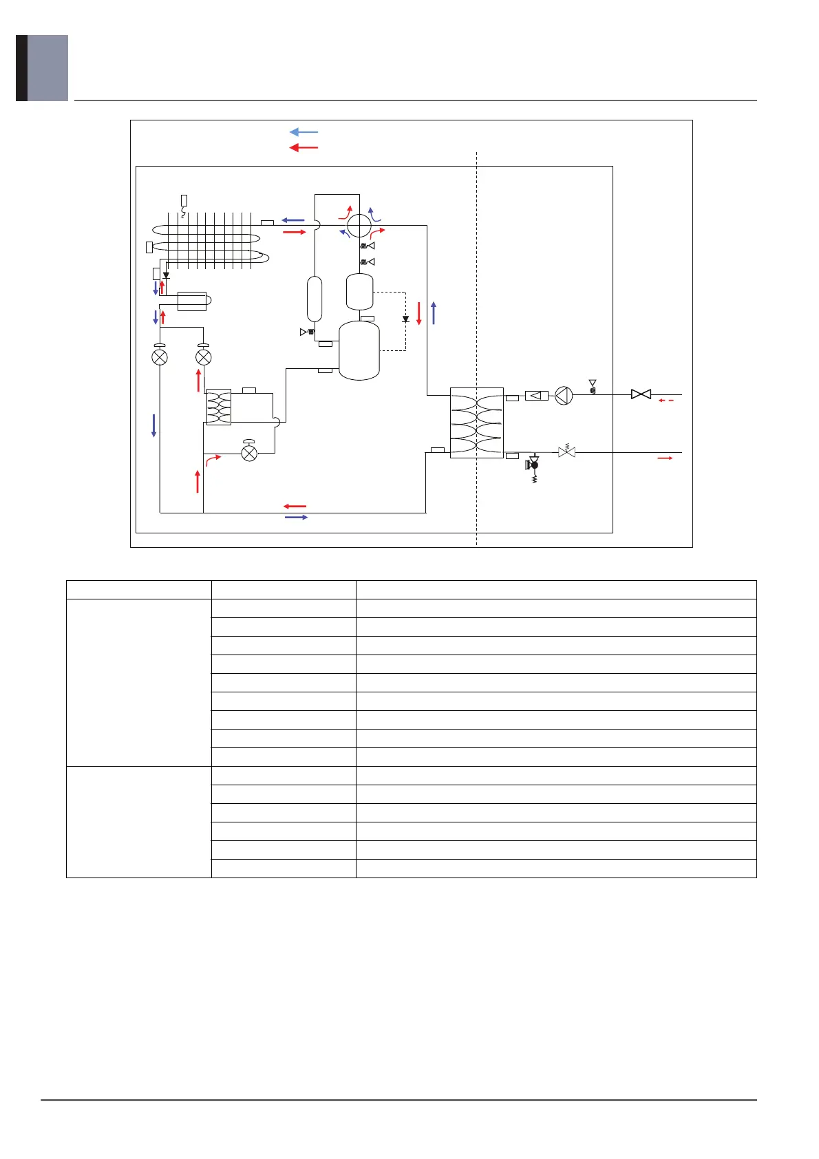
6. Piping Diagram
Category Symbol Meaning
Refrigerant side
S1 Outdoor-HEX gas temp. sensor
S2 Outdoor-HEX middle temp. sensor
S3 Compressor discharge temp. sensor
S4 Compressor suction pipe temp. sensor
S5 Outdoor-HEX temp. sensor
S6 Outdoor air temp. sensor
S7 Compressor-injection pipe IN temp. sensor
S8 Compressor-injection pipe OUT temp. sensor
S10 PHEX liquid temp. sensor
Water side
S11 Inlet water temp. sensor
S12 Outlet water temp. sensor
S17 Flow sensor
S19 Water pressure sensor
LP Low pressure sensor
HP High pressure sensor
: Cooling
: Heating
Accumulator
4 Way V/V
ll}X
ll}Y
ll}Z
pol
wol
Air Vent
Safety V/V
zXW
zZ
z^
z_
z\
zY
zX
z[
zXX
zXY
z]
ow
sw
zX^
zX`
<Outdoor Unit>
<Refrigerant Side>
Heat Sink
Check V/V
V
Check V/
Pressure
Sensor
Pressure
Sensor
Pressure
Switch
Seperator
vG
j
Flow
pu}G
Sensor
Water
Pump
Pressure
z
6WUDLQHU
$FFHVVRU\
Heating
Inlet
Heating
Outlet
 Loading...