28
Four-Way Ceiling Cassette System Engineering Manual
Due to our policy of continuous product innovation, some specications may change without notication.
© LG Electronics U.S.A., Inc., Englewood Cliffs, NJ. All rights reserved. “LG” is a registered trademark of LG Corp.
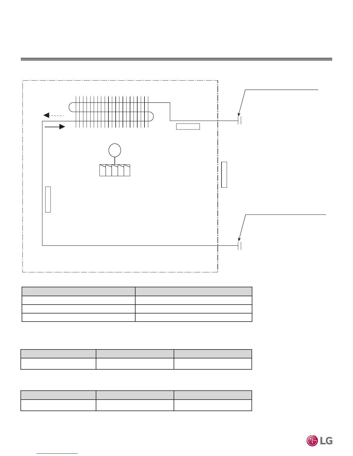
INDOOR UNIT REFRIGERANT FLOW DIAGRAM
LCN098, 128HV4
Figure 21: LCN098, 128HV4 Refrigerant Flow Diagram.
Table 8: Four-Way Ceiling Cassette Indoor Unit Thermistor Details.
Model No. Vapor (inch) Liquid (inch)
LCN098HV4, LCN128HV4 3/8 1/4
Table 9:
LCN098, 128HV4 4-Way Ceiling Cassette Indoor Unit Refrigerant Pipe Connections
Description (Based on Cooling Mode) PCB Connector
Indoor Air Temperature Thermistor CN-ROOM
Evaporator Inlet Temperature Thermistor CN-PIPE / IN
Evaporator Outlet Temperature Thermistor CN-PIPE / OUT
Heat exchanger
Gas pipe connection port
(flare connection)
Liquid pipe connection port
(flare connection)
Turbo fan
M
Cooling
Heating
Indoor Air
Temperature Thermistor
Evaporator Inlet
Temperature Thermistor
Evaporator Outlet
Temperature Thermistor
Table 10: LCN098, 128HV4 4-Way Ceiling Cassette Indoor Unit Refrigerant Pipe Sizes.
Model No. Vapor (inch) Liquid (inch)
LCN098HV4, LCN128HV4 3/8 1/4
 Loading...