58
Single Zone Mega and Mega 115V Wall Mounted Installation Manual
Due to our policy of continuous product innovation, some specifications may change without notification.
©LG Electronics U.S.A., Inc., Englewood Cliffs, NJ. All rights reserved. “LG” is a registered trademark of LG Corp.
ELECTRICAL SYSTEM INSTALLATION
Outdoor Unit Electrical Connections
Connecting Outdoor Unit Wiring
• Verify that main power is completely off and that no power is going through the Single Zone system before proceeding with these steps.
Follow all safety and warning information outlined at the beginning of this manual. Failure to do so will cause electric shock, bodily injury
and / or death.
• Per code, install a main indoor breaker, and an outdoor service disconnect that interrupts all power sources simultaneously. There is risk of
fire, electric shock, explosion, physical injury or death.
• Verify that the circuit breaker or some other emergency power cutoff device is in place before any power wiring is done to the system. Fail-
ure to do so will cause electric shock, bodily injury and / or death.
•
Never touch any power lines or live cables before all power is cutoff to the system. To do so will cause bodily injury or death.
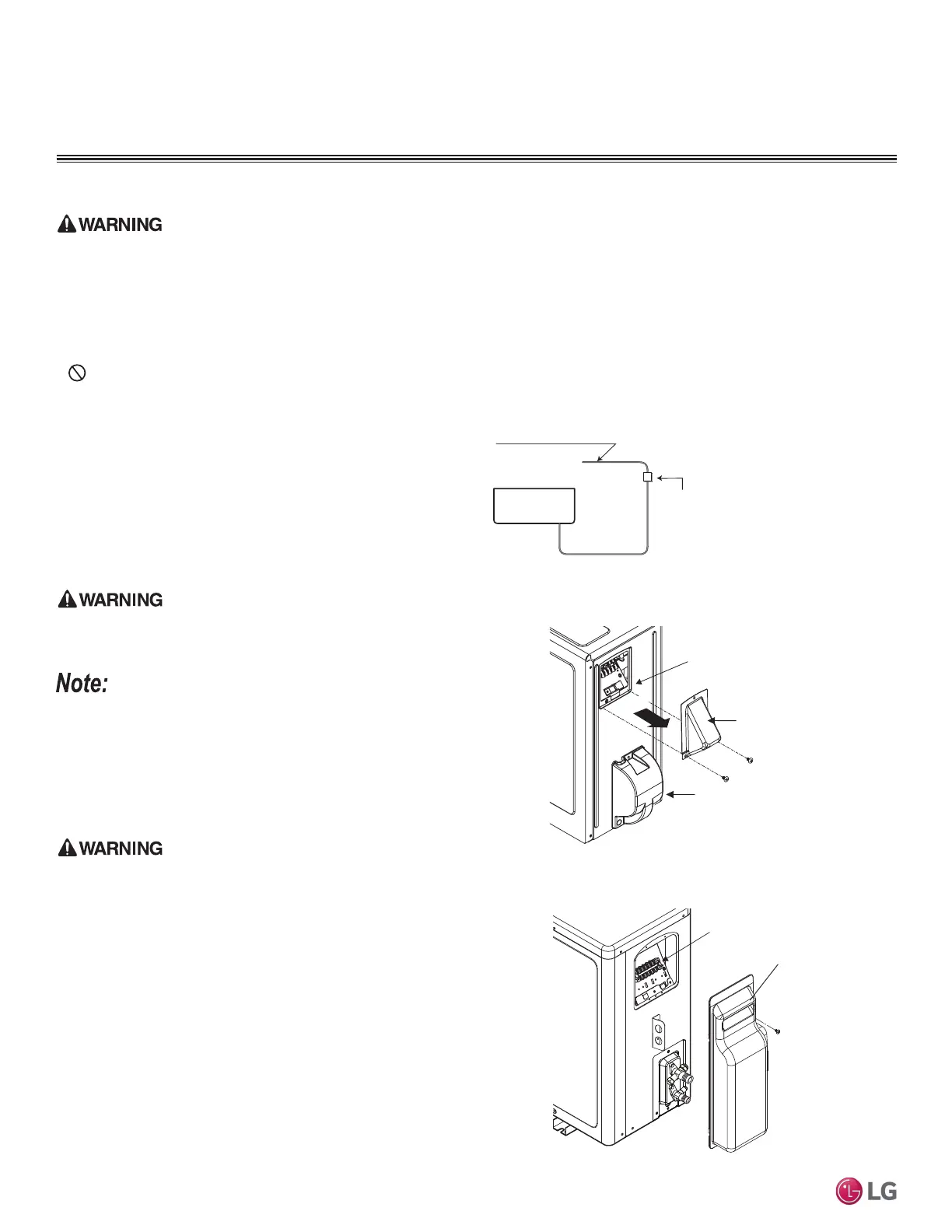
1. Using a Phillips head screwdriver, remove the piping / control box
cover or control box cover (depends on model) from the outdoor
unit.
2. Inspect all wiring inside the chassis to be sure they are secure
and have not loosen during transportation and installation of the
outdoor unit. Inspect wires for damage or cracks.
Loose, damaged, or cracked wires will cause electric shock, bodily injury
and / or death.
Loose wires can cause the wiring to burn out, damaging the outdoor
unit.
3. Confirm that electrical power supply capacity will be sufficient to
run the unit. Verify that a circuit breaker and service disconnect
are installed. See the Electrical table in the Product Data section
for details on electrical requirements.
Per code, install a main indoor breaker, and an outdoor service discon-
nect that interrupts all power sources simultaneously. There is risk of
¿UHHOHFWULFVKRFNH[SORVLRQSK\VLFDOLQMXU\RUGHDWK
4. Confirm that the right gauge size is used for all wiring. Follow all
federal, state, and local codes related to wiring.
5. Guide the power wiring to the outdoor unit, and communications
/ connection (power) cable from the outdoor unit to the indoor
unit, through the conduit holes on the outdoor unit or control box
cover (see images below and on the next page). Install conduits
to protect the wiring and cable.
Air
Conditioner
Main Power Source
Circuit Breaker
Use a circuit breaker
or time delay fuse
Figure 109: Circuit Breaker.
Terminal Block
Piping / Control
Box Cover
Figure 110: Accessing LSU090-120HEV2 and LSU090-120HXV Out-
door Unit Wiring Connections (Appearances Will Differ Depending on
Model).
Figure 111: Accessing LSU180-240HEV2 Outdoor Unit Wiring Connec-
tions.
Piping Connection
Cover
Control Box
Cover
Terminal Block