47
Electrical System Installation
Due to our policy of continuous product innovation, some specifications may change without notification.
©LG Electronics U.S.A., Inc., Englewood Cliffs, NJ. All rights reserved. “LG” is a registered trademark of LG Corp.
ELECTRICAL SYSTEM INSTALLATION
Communication / Connection (Power) Cable Specifications from Outdoor
Unit to Indoor Unit
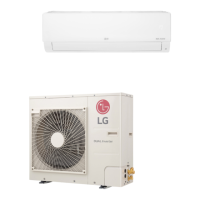
Figure 73: Typical Single Zone Outdoor Unit to Indoor Unit Wiring and
Communications Cable Diagram.
• Always verify the communication cable is connected to a communications terminal on the Single Zone unit. Never apply line voltage
power to the communication cable connection. If contact is made, the PCBs will be damaged.
• The shield of the communications cable connecting the outdoor unit to the indoor unit must be grounded only to the outdoor unit frame.
• Tie the shield of each cable segment together using a wire nut at the indoor unit. Maintain polarity throughout the communication network.
• Position the incoming power to the outdoor unit away from the power / communications cables from the outdoor unit to the indoor unit.
• Never use a common multiple-core communications cable.
Connections and Specications
7/16" ± 1/8"
13/16"
GN/YL
Power Wiring, Ground
to Outdoor Unit
Communication / Connection
(Power), Ground Cable
From Outdoor Unit
To Indoor Unit
GN/YL
GN/YL = (Ground, Yellow)
7/16" ± 1/8"
All power wiring and communication cable installation must be per-
formed by trained service providers working in accordance with local,
state, and National Electrical Code (NEC) / UL / ETL federal regulations
related to electrical equipment and wiring, and following the manufac-
turer product diagrams, requirements, and instructions in this manual.
Failure to do so will lead to electric shock which can cause physical
injury or death.
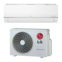
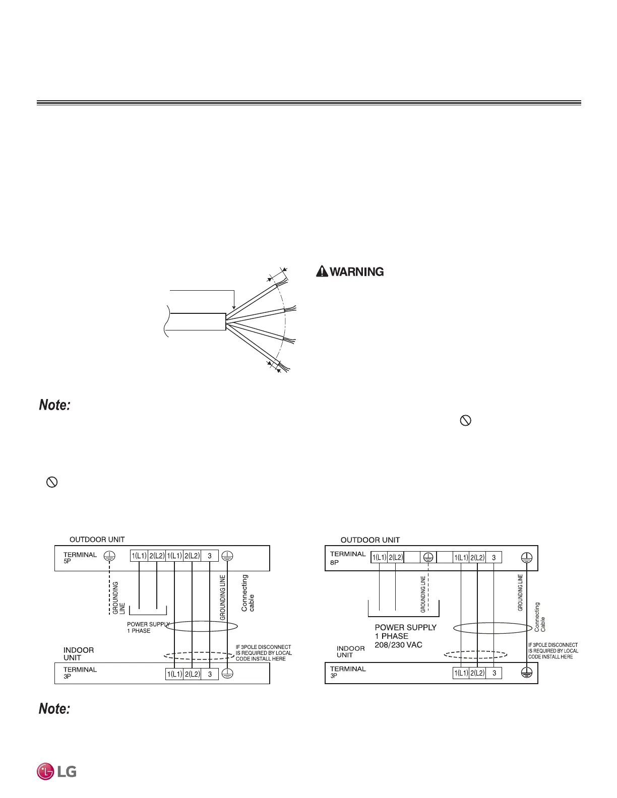
Figure 74: Typical LS090-120HSV5 Power / Communication System
Diagram.
• For communication / connection (power) wires between the Single Zone outdoor unit and the indoor unit, use a minimum 14 gauge, four (4)
conductor, stranded, shielded or unshielded wire. If shielded, the wire must be grounded to the chassis at the outdoor unit only.
• Insulation material as required by local code.
• Firmly attach the cable; provide slack but secure in a way to prevent external forces from being imparted on the terminal block.
• Wiring must be completed without splices.
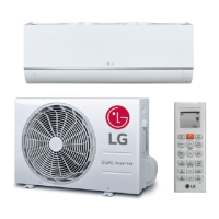
Figure 75: Typical LS181HSV5 Power / Communication System
Diagram.
• Use of 14 gauge, four (4) conductor, stranded, shielded or unshielded wire is allowed for lengths up to the published maximum pipe
length, plus recommended slack at both ends.
 Loading...